mobility scooter repair help

Thread Starter

helphelp

Joined Aug 18, 2011
8
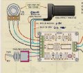
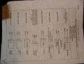
ok guys, i need help here. i'm attemptong to rewire a 3-wheeled scooter for an older gentleman i know. the scooter is a cheap chinese model. 24 volt, XYDH-036. apparently, there was a problem with the speed control cutting out so they bought an aftermarket contoller (SPD-24500R) that was supposed to work with this scooter. well, when they tried to install it, the wires didnt match up, so they began to cut connectors off, and lost track of where the wires were sopposed to run. so basically, i am trying to rewire the whole scooter starting from scratch.
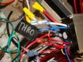
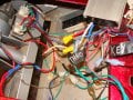
the problem i am having is that i cant seem to get the accelerator to regulate the speed of the motor. i have the original wiring diagram for the scooter, and the diagram that came with the speed controller, but of course, these do not match up. i have traced all of the wires in the harness of the scooter, and know where they all run to, the problem is, the connectors are cut on the new speed contoller, so i'm not sure what wires were supposed to go to where. the wires coming from handlebar for throttle are, red/black/green where the wires from the contoller are, red/black/blue. i have tried all combinations of these wires with no success.
i am by no means an electrical guru and any help would be greatly appreciated. thanks in advance for any help.
 

Thread Starter

helphelp

Joined Aug 18, 2011
8
yes, i have this diagram, but doesnt seem to correspond to wiring on scooter. like i said, the whole wiring on the scooter was cut up when i recieved it, so i am pretty much starting from scratch, which you would think would be easier, but i apparently cannot get it figured out yet. thanks in advance for any other help
 

iONic

Joined Nov 16, 2007
1,662
The problem i am having is that i cant seem to get the accelerator to regulate the speed of the motor.I have the original wiring diagram for the scooter, and the diagram that came with the speed controller, but of course, these do not match up.
We may need to see this.

the wires coming from handlebar for throttle are, red/black/green where the wires from the controller are, red/black/blue. i have tried all combinations of these wires with no success.
The throttle wires on the scooter are red/black/green. Is it a potentiometer or a hall-effects sensor. With a potentiometer you should read between zero and X ohms between black/red and black/green as you adjust the accelerator. It should be 2X from red to green.

You mention the throttle wires were red/black/blue on the new controller, but the diagram for it show black/red/blue. Was this a typo on your part? Is the connector intact on these wires? Perhaps these are not the correct three wires.
 

Thread Starter

helphelp

Joined Aug 18, 2011
8
the wire colors were listed in no specific order in last post. the connectors were cut off from the wires so it is a possibility that i have the wrong black/blue/red combination, but the others run the keyswitch, which seems to be working fine. i have one red which has constant power from the speed controller which i have run to the key? does this seem incorrect? when i turn on the key, the motor runs at full throttle, when i touch any of the wires coming from the throttle with a tester, the motor speed decreases, but i cant seem to find the right combination i guess. seems like my problem may be with other connection as there are only so many combinations to try with limited wires.
 

iONic

Joined Nov 16, 2007
1,662
With respect to the controller wires.

The Brake light and the Pilot light wires, both black and red and probably the same size. With power disconnected I would guess that you have continuity, red/red and black/black.
I'd suspect you would not have continuity with the red of the charger to any other red wire of the same size. The only other thin red wires are from the throttle and the keyswitch.

All blacks will have continuity.
Brake Lever Switch, Brake Light Connector, and Power Light Connector would probably have 24V red to black.
I'm guessing that the throttle wires do not have 24V, but maybe 5V from red or blue to black.

Just some assumptions that might help sort the wire out.
 
Last edited:

Thread Starter

helphelp

Joined Aug 18, 2011
8
ok, so here is an update.... I have elminated from the controller box the following wires: brakes, brake lights, and charger. i am now left with 3 reds, 2 blues, 2 blacks, and one yellow (which i know runs to keyswitch). one of the red wires has 24v in it, and the other two seem to have nothing. it would seem that the right combination of these wires MUST be there. i would like to think i can get this thing going, but it seems my lack of electrical knowledge is holding me back a bit on this one. i greatly appreciate all the help i have recieved so far, and i hope to report to you guys soon that i got it figured out. oh wel, keep plugging away for now i guess. thanks again for all the help
 

debe

Joined Sep 21, 2010
1,389
Your original post says you have the original circuit of the scooter. Whynot post it here? Also a few good clear pictures of the actual controler(throttle) & any circuit board that may be with it. Also on the replacement controller when conected to power, check the throttle conector & see if there is a voltage betwean red/black or blue/black.
 

iONic

Joined Nov 16, 2007
1,662
ok, so here is an update.... I have elminated from the controller box the following wires: brakes, brake lights, and charger. i am now left with 3 reds, 2 blues, 2 blacks, and one yellow (which i know runs to keyswitch). one of the red wires has 24v in it, and the other two seem to have nothing. it would seem that the right combination of these wires MUST be there. i would like to think i can get this thing going, but it seems my lack of electrical knowledge is holding me back a bit on this one. i greatly appreciate all the help i have recieved so far, and i hope to report to you guys soon that i got it figured out. oh wel, keep plugging away for now i guess. thanks again for all the help
So you have 3 red, 2 blue, 2 black, 1 yellow.
The keyswitch needs the yellow, 1 blue and 1 red
this leaves 2 red, 1 blue and 1 black

Either the Brake light, or pilot light should use the 24V, check the brake light for the voltage rating on the bulb.

You could also measure all the blue with a black to see if there is any voltage there.
 

Thread Starter

helphelp

Joined Aug 18, 2011
8
ok, so i took a few snapshots of what i have so far. pics are of original wiring diagram, and replacement speed controller wiring. the rest of the pics are shot of the wires and the controller, which prob look really messy to you guys, but if it helps anyone diagnose my mistake, then its worth a shot. no matter how i hook it up, i am always left with one extra red wire, and one extra black wire. again, thanks for all of the help.
 

Attachments

debe

Joined Sep 21, 2010
1,389
The first problem I suspect is the original circuit uses 2 relays to reverse the motor, the new controler doesnt use relays probably uses a H bridge. The thick Blue & White wires from the new controler you have run to the relays, try runing the wires directly to the motor, dont use the relays. (Its nearly mid night here & im of to bed soon )
 
Last edited:

Thread Starter

helphelp

Joined Aug 18, 2011
8
ok, that could help out a lot. only thing is, should i run the big black/red wires directly to battery to bipass the relays? cause the diagram for the controller says the large blue/white run the motor, not the large black/red. i opened up the controller to try to trace the wires, but i cant seem to get a clear pic of the codes on the circuit board. i will make a list of wires and codes and post it soon. that should eliminate any doubt, assuming someone can help me with the codes. i'm charging up the batteries right now to have another go at it.
 

debe

Joined Sep 21, 2010
1,389
Your right I got the wrong colours & corected my prev post. The thick Red & Black go to the battery, the red is fused. & run the Blue & White to the motor & see how you go with that.
 

Thread Starter

helphelp

Joined Aug 18, 2011
8
i tried the wiring as you had suggested and now im getting full speed in forward with no reverse and still no throttle response?
i have opened the controller, and took a look at the circuit board. i could not get a clear pic of the board with wires and codes so i will do me best to describe the codes and corresponding wires (hoping that someone knows what the codes mean)
starting from the right side of the board:
1 blue wire connected to code ZB?
1yellow,1black wire connected to code sc.(which should go to brakes because the connector is still on those)
3 black wires connected to code GND.(which i can figure out means ground)
1 red wire connected to code 5v.(which i was using as red for the throttle?)
2 red, one yellow wire connected to code dm? (not sure about these but the yellow runs the key)
2 red wires connected to code vcc.( one of which runs to charge connector that is still on the wires) these seem to have constant power
1 blue connected to code dc.
i hope someone can figure out my mess because i want to get this thing running and out of my garage. Thanks again for all the help, you guys are great!
 

debe

Joined Sep 21, 2010
1,389
Pretty sure the Red 5V will be throttle, The other 2 wires to the throttle being Green & Black. Just a guess as the original wiring is Green negative battery, is the green wire from the throttle Gnd & the Black the speed signal? Or the other way round?
 

Thread Starter

helphelp

Joined Aug 18, 2011
8
there is no green wire that comes from the controller. i have 5v red connected to red from throttle control, black/black, and green from throttle to blue from controller. no matter if i switch the blue wires between key/throttle, i still get the same response. now i have full speed forward, no reverse, and no throttle response. i can regulate speed with the brake levers, but that doesnt seem too safe to me. think i'm going to take a break for a bit from this project, it is driving me nuts. keep the help comming, i really do appreciate it all. i think if i had a clue as to how this stuff worked, i would have already figured it out, but then again, i wouldnt need to be on here asking questions either. thanks again
 

iONic

Joined Nov 16, 2007
1,662
You've got all the colors and wires to make yourself a rubics cube of a project. I think the best of us would be sitting right where you are now.

dede's thoughts about bypassing the relays sound pretty reasonable. It's funny how they did not inclose them in the controller unit itself. You ought to consider troubleshooting the two relays, because if one is gone, neither of them will operate in the diagram as wired and you will end up with a scooter with no GO. It might be the problem you are trying to fix in the long run as opposed to the controller.

A piece of advice: don't try to open the controller you purchased as doing this will more than likely break it. I did this to one I bought from the same place (one I toasted) and it is encased in black plastic goop so that you can't reverse engineer their cheep design.
 
Last edited:

AMK4

Joined Mar 28, 2015
12
there is no green wire that comes from the controller. i have 5v red connected to red from throttle control, black/black, and green from throttle to blue from controller. no matter if i switch the blue wires between key/throttle, i still get the same response. now i have full speed forward, no reverse, and no throttle response. i can regulate speed with the brake levers, but that doesnt seem too safe to me. think i'm going to take a break for a bit from this project, it is driving me nuts. keep the help comming, i really do appreciate it all. i think if i had a clue as to how this stuff worked, i would have already figured it out, but then again, i wouldnt need to be on here asking questions either. thanks again
 
Top