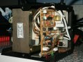
Any experience fixing an Pihsiang MB-24/3 mobility power supply would be gratefully received as new ones are exorbitantly priced.
These units are for charging the 24V batteries in mobility scooters.
The faulty one appears to have an intact transformer with a CT 60-0-60 main secondary and a much lighter 10-0-10 for the control electronics. The main 20A output fuse is also intact.
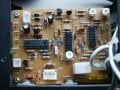
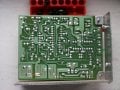
The control appears to be using two BT151 thyristors in a biphase rectifier (not smoothed) arrangement with the main secondary.
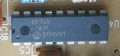
The control circuitry comprises two HA17324 ICs, which I think are equivalent to LM324 quad op amps.There is 18 pin DIL IC which I do not recognise, labelled CF74S an ??47P. I think this is a PIC processor.
These units are for charging the 24V batteries in mobility scooters.
The faulty one appears to have an intact transformer with a CT 60-0-60 main secondary and a much lighter 10-0-10 for the control electronics. The main 20A output fuse is also intact.
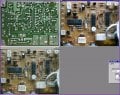
The control appears to be using two BT151 thyristors in a biphase rectifier (not smoothed) arrangement with the main secondary.
The control circuitry comprises two HA17324 ICs, which I think are equivalent to LM324 quad op amps.There is 18 pin DIL IC which I do not recognise, labelled CF74S an ??47P. I think this is a PIC processor.