Mobility Scooter - how does brake circuit work in a golf cart?

Thread Starter

cspwcspw

Joined Nov 8, 2016
78
Hi - I'm looking at a golf scooter donated to a friend, for use as a mobility scooter. But two or more people fiddled with the non-working throttle and controller before me, including replacing at least one MOSFET with a bad soldering job. There is no longer any throttle mechanism, nor a charger. Don't ask! My local electronics friends (we tend to do microcontroller projects) have suggested "just gut it and build your own controller from scratch" which I may ultimately need to do... But for now, I'm learning a bit and having some fun trying to figure out some things.

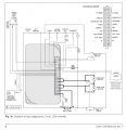
The not-working controller is a Curtis 1228-2730, capable of 110 Amps at 24 V. The controller is for full four-quadrant operation, can drive forward or reverse and can handle regenerative braking. The cart and the motor are unbranded, other than it says 24V G2-2A which is hand- engraved on the cover plate. It looks like all-in-one-assembly motor/transaxle/differential/brake, like some I can find online from China.

The PIC microcontroller outputs some flashing LED patterns for indicating errors. Some of these make sense, so something works okay. For example, if I mechanically release (bypass) the brake in the motor (which also opens an internal switch in the brake circuit in the motor), or I disconnect the brake circuit, the controller gives me "brake fault" LED patterns. And I can provoke a few other error situations - e.g. attempt to start the cart with the throttle open. But I also get a pattern that isn't on the diagnostic menu (2, 2) that I can't clear. And I cannot replicate on my workbench what it does in the cart - periodic clicking noises from, I think, the relay in the controller, about 70 per minute. I have what are supposed to be dummy brake circuits and motor loads on the controller on my workbench, but its evidently not the same.

Anyway here is the question: I'm wanting an overview (a guess really) of how this brake circuit typically interacts with the motor drive circuit. There are separate wires into the motor for the "brake" and its only rated at 1 Amp in the controller specs. So
a) when does the brake engage? Is this purely to hold the vehicle still while you sink your putt on the green?
b) is it likely binary (on/off) or can one apply more or less current to partially brake via this mechanism?
c) is it mechanical? And by default, somehow when you turn the cart off, should the brake remain engaged?

I did find somewhere in my readings that part of setting the controller throttle parameters one should slowly open the throttle until one hears the click (which I think is supposed to be the brake disengaging). That would mean "binary, mechanical, brake engaged when no power", I guess. I think the settable parameter is a threshold that says "don't push power through the motor until you're close to getting the brake off".

Any hints or big-picture stuff or places to read where I can get some handle on this will be useful.

My next step is to try to get the serial interface working to the controller and see if I can get better diagnostics. I don't have access to a Curtis diagnostic programming tool, but there is some PC software that looks like it can do the job if I can get the USB to serial link up.

Thanks for any help.
Peter
 

Attachments

MaxHeadRoom

Joined Jul 18, 2013
28,576
It appears when ever one of the motors is enabled, the other is shorted (in braking), at least that is the way it looks to me.
Max.
 

GetDeviceInfo

Joined Jun 7, 2009
2,192
I’ve seen a number of applications where a mechanical brake within the motor, is normally on, powered off. Brake source is either motor power, or separate control. So if you are not powering the motor, brake is on. I suspect on regen, the brake is released on over speed.
 

Thread Starter

cspwcspw

Joined Nov 8, 2016
78
You can use regenerative braking (or just shorting the motor with a heavy duty resistor). You can also have ordinary drum or disk brakes.

Here's a discussion. Search on "brak." http://www.4qdtec.com/bridge.html
Thanks. I found this reference answered some questions I had: When you're controlling the motor with PWM chopping, do you chop both the MOSFETs in the path, or just one? Turns out he chops just one. And the chopping is done low-side, which is not how I imagined it, although I had not given it any thought. And when your cart is trundling forward down the hill faster than you're driving it, what is the polarity on the motor? And what current flows? Where does it flow to? So very useful, exactly the kind of thing I was hoping to find. Thanks.
 

MaxHeadRoom

Joined Jul 18, 2013
28,576
Thanks. I found this reference answered some questions I had: When you're controlling the motor with PWM chopping, do you chop both the MOSFETs in the path, or just one? Turns out he chops just one. And the chopping is done low-side, which is not how I imagined it, although I had not given it any thought. And when your cart is trundling forward down the hill faster than you're driving it, what is the polarity on the motor? And what current flows? Where does it flow to? So very useful, exactly the kind of thing I was hoping to find. Thanks.
A DC motor that is back-fed mechanically, will generate, this is how regenerative braking works.
Max.
 

Thread Starter

cspwcspw

Joined Nov 8, 2016
78
A DC motor that is back-fed mechanically, will generate, this is how regenerative braking works.
Max.
Thanks. What remains a bit fuzzy for me is control of the generated current. Braking force depends on presenting a load to the "generator". If I understand, that braking load varies - controlled again by chopping the MOSFETS. So the controller apparently exercises dynamic power control and overload protection in all four quadrant cases: forward drive; backward drive; forward braking; and backward braking.
 

Thread Starter

cspwcspw

Joined Nov 8, 2016
78
I'm still tinkering and still in DIY mode. So I have a motor (all-in-one transaxle assembly with brake, differential, and I assume some gearing), from this golf scooter. Unbranded, labelled for 24V. How can I estimate a) current I might need to supply. The scooter came with this non-functional controller that advertises peak 110A. And b) the wattage / HP of the motor. Are there some obvious "lab tests" or signs like resistance, inductance, the brushes, etc. Or can I try to run the motor asking it to lift 1Kg through 1 Meter in 1 second (ok, that's obviously too fast!) Or if I plot the load vs the amps needed to lift it, will I get some idea? Is it helpful just to supply 24V at whatever the motor can handle, and use that as an upper limit? Must the motor be under mechanical load? Can I weight the motor and get some likely upper/lower bounds?

Thanks for any hints on "how do I know what this motor is capable of?"
 

MaxHeadRoom

Joined Jul 18, 2013
28,576
So are you using this assembly for another purpose it was intended for?
If so, what are the requirements for the new application, what gearing applies, if any, on the existing set up.
Measure the current with zero load first.
Max.
 

MrChips

Joined Oct 2, 2009
30,618
Calculate the torque required, not by using the 1m lift required but the radius of the wheel or drum lifting the load.
1N-m is about 10 kg-cm

1592413909794.png
 

Thread Starter

cspwcspw

Joined Nov 8, 2016
78
So are you using this assembly for another purpose it was intended for?
If so, what are the requirements for the new application, what gearing applies, if any, on the existing set up.
Measure the current with zero load first.
Max.
Thanks for interest.

It's not being used for a different purpose - the intended use is to get the golf scooter working for use as a mobility scooter. So the existing gearing, RPM, tyre size, motor size, etc. I assume is "fit for purpose". But I'm not making much progress with the existing controller that doesn't work (and I suppose its advertised 110A peak rating at 24V might be sensibly matched for original purpose.) So I'm considering doing my own controller / following some of the open source controllers. The two open source ones I've looked at so far are for much higher-power EVs. So knowing a bit more about the capabilities of the motor will be a sensible starting point for sizing my requirements, I thought.

The Curtis controller uses 8 power Mosfets IRF 3205s and pulse width power control with an HIP4082 H-Bridge Mosfet driver. I just happen to have a handful of the Mosfets available. I'll have to get an H-Bridge driver - we're still locked down here with problems in a lot of supply lines. I have worked with the IFR3205 before, and have done some PWM control and power feedback on an Arduino (I'll use a Mega that I have lying around this time so I don't run out of space so quickly). So my rough emerging idea for power control is to "replicate" more or less what Curtis did - a 4-quadrant controller, two Mosfets paired high-side and two paired low-side on each leg of the motor, flyback diodes, etc. And an H-bridge driver with four channels.

For me it remains primarily a DIY hobby project where I'm trying to learn a bit more about "higher power" apps and motor control. So the learning / maker aspect is as interesting as trying to get the scooter going again. And it's a retirement project, so I don't need to conserve or optimize my time. Of course my friend thinks differently - she just would like this donated mobility scooter to work, but it has been lying around dead for a very long time already!
 

Irving

Joined Jan 30, 2016
3,841
Hi,

If you haven't found it yet, I suggest you take a look at the Wheelchairdriver.com forum where you'll find people with knowledge of all this kit and info on cables, interfaces and programming the Q-Logic controller.

Braking is entire regenerative. The physical solenoid brake on the motor is a parking brake only, and is powered to release when the throttle is opened more than a couple of %. You can fool the controller that the brake is present if there's a o/c coil with typically a 100 - 150ohm resistor. The brake switch is an inhibit to prevent the controller powering the brake solenoid and the motor when the mechanical brake is applied. Depending on programming the seat lift may not function unless the mechanical brake is applied. There may also be an inhibit switch on the seat lift to reduce max speed to typically 2mph when seat raised. I don't see that on the wiring diagram and obviously the seat lift and traction motors are using the same H-bridge switched by the seat lift relay so you can't do both at once.

The wattage mentioned on the motor is not the max output power. On mobility devices its usually the continuous losses the motor can tolerate without overheating and will typically be 180 - 250W. A transaxle scooter will take around 5 - 10A when running at speed on a good flat surface, but 90+A climbing a curb or its max rated incline paticularly on soft terrain and the controller allows a few seconds boost to 110A if things get sticky but will throttle back to 80A or less if it overheats, which they do quite easily.

The typical impedance of the motor, assuming its a 2-pole one, will be around 50 - 100milliohm and its torque something like 10 - 15Nm at the wheel. Typical motor revs are 2100 - 3300 geared down for typically 4, 6 or 8mph, sometimes higher, depending on model and it also depends on wheel size which can be 6, 8 , 10 , 12 or 13 inches. Golf scooters tend to have larger 12 or 13 inch wheels and wider tyres (4 or 5 inch) to avoid damaging the turf and are heavier & wider than mobility scooters, and therefore don't generally physically fit indoors or in shopping centres/malls, whereas a typical mobility scooter will have 2 inch wide, 8 or 10 inch diameter wheels and will be less than 26 inch/600mm wide, but there are many variations.

Its not clear whether this is a mobility scooter or a golf scooter and where you are in the world? If it is a golf scooter it generally can't legally be used on public roads or sidewalks (US)/pavements (UK) and mobility scooters often have other restrictions such as requiring a switch restricting speed to 4mph.
 

Thread Starter

cspwcspw

Joined Nov 8, 2016
78
Hi,

If you haven't found it yet, I suggest you take a look at the Wheelchairdriver.com forum where you'll find people with knowledge of all this kit and info on cables, interfaces and programming the Q-Logic controller.

Braking is entire regenerative. The physical solenoid brake on the motor is a parking brake only, and is powered to release when the throttle is opened more than a couple of %. You can fool the controller that the brake is present if there's a o/c coil with typically a 100 - 150ohm resistor. The brake switch is an inhibit to prevent the controller powering the brake solenoid and the motor when the mechanical brake is applied. Depending on programming the seat lift may not function unless the mechanical brake is applied. There may also be an inhibit switch on the seat lift to reduce max speed to typically 2mph when seat raised. I don't see that on the wiring diagram and obviously the seat lift and traction motors are using the same H-bridge switched by the seat lift relay so you can't do both at once.

The wattage mentioned on the motor is not the max output power. On mobility devices its usually the continuous losses the motor can tolerate without overheating and will typically be 180 - 250W. A transaxle scooter will take around 5 - 10A when running at speed on a good flat surface, but 90+A climbing a curb or its max rated incline paticularly on soft terrain and the controller allows a few seconds boost to 110A if things get sticky but will throttle back to 80A or less if it overheats, which they do quite easily.

The typical impedance of the motor, assuming its a 2-pole one, will be around 50 - 100milliohm and its torque something like 10 - 15Nm at the wheel. Typical motor revs are 2100 - 3300 geared down for typically 4, 6 or 8mph, sometimes higher, depending on model and it also depends on wheel size which can be 6, 8 , 10 , 12 or 13 inches. Golf scooters tend to have larger 12 or 13 inch wheels and wider tyres (4 or 5 inch) to avoid damaging the turf and are heavier & wider than mobility scooters, and therefore don't generally physically fit indoors or in shopping centres/malls, whereas a typical mobility scooter will have 2 inch wide, 8 or 10 inch diameter wheels and will be less than 26 inch/600mm wide, but there are many variations.

Its not clear whether this is a mobility scooter or a golf scooter and where you are in the world? If it is a golf scooter it generally can't legally be used on public roads or sidewalks (US)/pavements (UK) and mobility scooters often have other restrictions such as requiring a switch restricting speed to 4mph.
Really helpful, thanks Irving. Helps me understand the ballpark numbers. I subsequently also thought that just looking at the SWG of the drive cables into the motor would also give some idea. They're about the same size as my home wiring for wallplugs. I'll look at that Wheelchair group too.

I did make some small progress yesterday on understanding the brake - yeah, its a solenoid, I can get it to pick at about 17V @ 200ma. Has much hysteresis - it only drops again at about 1V @ 10ma. My simulated high-power resistor also works on the bench, and the controller does pick up that the brake is missing or mechanically disengaged and shows the appropriate error codes on the LED diagnostic. So it has clarified that aspect somewhat. However, to date, I've not been able to get the controller to pick the brake solenoid - I just used a bench power supply. My next plan is to get the motor to run with some homebrew PWM control. My bench PSU is a lightweight 2A device, (I've not done power / motor related stuff in the past). and 2A just gets me nowhere. So I'll rig up at least one power mosfet and some PWM on an Arduino, and use batteries.

This is a single-rider 4-wheeler golf cart, fat tyres, etc. My friend also has/had a three-wheeler tricycle that they used for a visit to the US, and was legal on sidewalks, malls, Disneyland, etc. But it went out of favour after she tipped over once or twice (and apparently the charger is no longer working, so they're lining up a second job for me). We're in a tiny place - Grahamstown, South Africa. The cart is too big to take to a shopping mall or transport in a car unless they get a trailer, so the intended use is for her and her hubby to take walks/rides around some nearby sports fields, and perhaps further afield if they get a trailer. We have a disused train line close by too, and I've long thought that putting something motorized on the tracks would be fun. Hubby was a fitter/turner/maintenance tech before he retired, so I can "delegate" the mechanical issues.
 

Irving

Joined Jan 30, 2016
3,841
You'll probably need at least 10A at 24v to get that motor started against the inertial loading of the gearbox and wheels and 5A+ to keep going.

Scooter power wiring is typically 12AWG for average 40A+ and 90A peak for <10sec typically.

Charging is through through the XLR connector at typically 8A max from a suitable mobility charger.

Use the existing batteries for testing. If you don't have the 24v charger, connect them in parallel + to + and - to - and use a 12v charger for at least 16 hours
 
Top