 Facebook
 Google
 GitHub
 Linkedin
Hello,
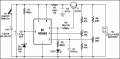
i found a mobile cellphone charger circuit with 555 timer. my goal is to make the circuit charge the phone battery to 5 volts with 2 amper, and than to stop the signal from the output(3) when the battery is charged with 5 volts. i understand that i need a lower zener diode breakdown voltage, and to change the trimmers resistance value. my first question is:
when the battery is charged with 5 volts it is going to discharge the current throw R4 R6 R5 VR1 VR2, better option is to increase their value so the current would be lower when its discharge? could this effect the 555 timer output?
second quesstion: what is the role of C1?
third question:
is there a way to add a led diode when its full charged? in this circuit the led diode goes off when the battery charged.
Thanks.
https://electronicsforu.com/electronics-projects/hardware-diy/mobile-cellphone-charger
Attachments
-
 6.9 KB Views: 9
Last edited:


