Facebook
 Google
 GitHub
 Linkedin
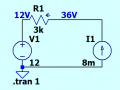
Here is the problem.

First I assign polarity.

Then KVL, E - IR1 - Vs = 0, 12V + -24V + -Vs = 0, .: Vs = 12V + -24V = -12V? BUT! 12V + -24V + -12V = -24V! and not 0 so...
Have I made a mistake in assigning polarity or...?
Also, why only multiply R1 by the current from the current source and not also add in the current from E?
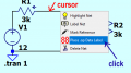
I also put it into LTS but then also confusion with which way the elements are placed with the correct current direction...
First I assign polarity.
Then KVL, E - IR1 - Vs = 0, 12V + -24V + -Vs = 0, .: Vs = 12V + -24V = -12V? BUT! 12V + -24V + -12V = -24V! and not 0 so...
Have I made a mistake in assigning polarity or...?
Also, why only multiply R1 by the current from the current source and not also add in the current from E?
I also put it into LTS but then also confusion with which way the elements are placed with the correct current direction...