Facebook
 Google
 GitHub
 Linkedin
Hello, my friends.
I recently bought an old 2mhz function generator, however, it doesn't work very well.
When I opened it for the first time, I noticed that some components were burnt (resistors and transistors), I immediately replaced them, it "works" but shows a lot of heat in this region (figure 01).
Apparently it was a "white label" project in which companies registered with their brand, but it shares the same project with other names: VC 2002, MFG 4202, GV 2002.
I'm a beginner and would like some help on possible problems and, mainly, techniques for identifying a problem in general.
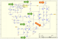
I have part of the electronic diagram of the device (I couldn't find the complete diagram), however, I have exactly the part that "roasted" and that after replacing the skins, it became very hot (figure 02).
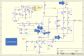
Figure 03 is a complement to the circuit and is one of the only two things I found on the internet.
Thanks!

# Figure 01:

# Figure 02:

# Figure 03:

I recently bought an old 2mhz function generator, however, it doesn't work very well.
When I opened it for the first time, I noticed that some components were burnt (resistors and transistors), I immediately replaced them, it "works" but shows a lot of heat in this region (figure 01).
Apparently it was a "white label" project in which companies registered with their brand, but it shares the same project with other names: VC 2002, MFG 4202, GV 2002.
I'm a beginner and would like some help on possible problems and, mainly, techniques for identifying a problem in general.
I have part of the electronic diagram of the device (I couldn't find the complete diagram), however, I have exactly the part that "roasted" and that after replacing the skins, it became very hot (figure 02).
Figure 03 is a complement to the circuit and is one of the only two things I found on the internet.
Thanks!
# Figure 01:
# Figure 02:
# Figure 03:
Attachments
-
160 KB Views: 11
-
41.5 KB Views: 11