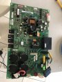
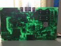
Assuming you have power input and the two fuses are OK and that there is no power reaching the big bridge rectifier (on the other side of the board) look carefully at the tracks and the solder joints between the input and the bridge. Also there should a common mode choke which you should check. That might be the large black rectangle about half way up the board from the fuses.
Assuming you have power input and the two fuses are OK and that there is no power reaching the big bridge rectifier (on the other side of the board) look carefully at the tracks and the solder joints between the input and the bridge. Also there should a common mode choke which you should check. That might be the large black rectangle about half way up the board from the fuses.
Fuse going to relay they have supply but going to rectifier is 0 volts i change already the relay but its the same....thank you so much for your reply sir.God Bless you more
The route from the fuses to the bridge rectifier should be short and obvious to trace.
Do a little reverse-engineering and it should may be clear it up?
Max.
The route from the fuses to the bridge rectifier should be short and obvious to trace.
Do a little reverse-engineering and it should may be clear it up?
Max.
Unfortunately not for that board.
But as two of us has said, do a little reverse engineering, do you have a meter?
There cannot be too much between power in and the bridge.
Max.

 Facebook
 Google
 GitHub
 Linkedin
 292.3 KB Views: 36