Microphone headset PA issues, trying to learn but need guidance

  • Thread starter Deleted member 828423
  • Start date

Thread Starter

Deleted member 828423

Joined Dec 31, 1969
0
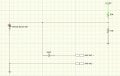
Hi all, below is the basic way I have wired up a headset comms system (CIRCUIT 1). It works but the volume is too low and have to yell into the mike, but when the mic is pressed firmly against my lips and I talk softly it’s a fair bit louder.

After doing some digging around I found allot of examples had a 1uF capacitor and a 10KΩ resistor (CIRCUIT 2).

I’m an auto electrician and this is outside my electronics education,
1) I don’t understand the use/ reason of the capacitor nor what type of capacitor is best used in this scenario
2) I don’t understand why the MIC - goes to ground and also to the PA AMP (CIRCUIT 2)

If anyone is able to help educate me I would really appreciate it, I have looked at doing courses in electronics or audio electronics to expand my knowledge but the number of different types of courses and subjects becomes daunting and overwhelming (yes I’m on the spectrum).


(CIRCUIT 1)AAC0688C-A7F7-427D-A189-8824A64069D8.jpeg


(CIRCUIT 2)
357F8A25-B961-4645-9AF6-5C89994D6FCC.jpeg
 

Attachments

LowQCab

Joined Nov 6, 2012
4,023
It's impossible to comment with such sparse information.

The second Schematic is a standard scheme for
providing Power to an "Electret-Condenser-Microphone",
the Capacitor blocks DC-Voltage,
but allows AC-Voltage to pass through to the Mic-Pre-Amp,
of course that's assuming that your Mic-Pre-Amp expects to see the
particular AC-Signal-Amplitude that your particular Microphone produces.

Is there a Gain-Adjustment, (Volume-Control), on the Mic-Pre-Amp ?

What type of Microphone was the Mic-Pre-Amp designed to work with ?

Does the Mic-Pre-Amp provide a DC-Bias-Voltage appropriate for an Electret-Condenser-Mic ?,
or was it designed for a "Moving-Coil" type Microphone ?

How far away is the Microphone from your mouth ?,
a "Noise-Canceling" Microphone will not work more than about ~3-inches from your mouth,
and should preferably be kept at about a ~1-inch distance.
.
.
.
 

Thread Starter

Deleted member 828423

Joined Dec 31, 1969
0
It's impossible to comment with such sparse information.

The second Schematic is a standard scheme for
providing Power to an "Electret-Condenser-Microphone",
the Capacitor blocks DC-Voltage,
but allows AC-Voltage to pass through to the Mic-Pre-Amp,
of course that's assuming that your Mic-Pre-Amp expects to see the
particular AC-Signal-Amplitude that your particular Microphone produces.

Is there a Gain-Adjustment, (Volume-Control), on the Mic-Pre-Amp ?

What type of Microphone was the Mic-Pre-Amp designed to work with ?

Does the Mic-Pre-Amp provide a DC-Bias-Voltage appropriate for an Electret-Condenser-Mic ?,
or was it designed for a "Moving-Coil" type Microphone ?

How far away is the Microphone from your mouth ?,
a "Noise-Canceling" Microphone will not work more than about ~3-inches from your mouth,
and should preferably be kept at about a ~1-inch distance.
.
.
.
At the moment there is no pre-amp in the circuit, it was going directly to the +MIC input & GND input on the speaker that has an internal amplifier. The four wires in the speaker connector was
12v+
PTT
GND
SMEG (which I have no idea what that stands for but has worked being MIC + with Voltage supplied through the resistor)

The headset is located inside a motorcycle helmet so the mic sock was touching my lips when speaking through it (headset specifications are below)

The pre-amp I’ve bought that I was going to use is below as is the specs for the headset kit1F21BF29-CFD3-437B-948A-68037D467FA1.jpeg4204C5B7-255F-41BD-952E-0B28580AB69D.png
 

Audioguru again

Joined Oct 21, 2019
6,672
I think that the 10k resistor value is too high and causing not enough voltage on the mic. Therefore the mic barely works.
Most electret mics draw a max current of 0.5mA and need a minimum of 2V across the mic. But your 10k resistor has the entire 5V across it leaving no voltage or a voltage too small for the mic. Try 4.7k or 5.6k ohms.
 
Last edited:

Thread Starter

Deleted member 828423

Joined Dec 31, 1969
0
Bellow is the original way the circuit has been wired up with more than 3 volts across the MIC3CF21D24-E384-428A-B614-3C7FB7F60082.jpeg
 

Audioguru again

Joined Oct 21, 2019
6,672
The 50k resistor from +12V does not produce enough current for the electret mic to have 3V and the resistor passes a lot of the +12V noise to the amplifier. The amplifier mic input probably already produces enough of a suitable smoothed voltage for the mic.
 

Thread Starter

Deleted member 828423

Joined Dec 31, 1969
0
Okay I’m at Witt’s end, I need help please, due to my spectrum issues I cant learn from reading I can only learn by doing and all the information, tutorials and work books overwhelm me with more information than I can handle or process and go too in-depth to unrelated matters.

I cant find simple answers or straight forward information for in-depth topics (I know just humour me) the circuit works, but I want to increase the sensitivity of the mic so the amplification is louder for the PA with out have me need to shout with the mic practically in my mouth. With the mic sock touching my lips and talking normally there is little to no audio/ amplification coming out of the PA (has internal amplifier).

I don’t know how to achieve my goal or what it is that I’m overlooking. Below is the only specs I have for the microphone and I have no reply ability to interpret what that informations represents.

There is also currently how the circuit is wired up.

Anyone who can please help it would be extremely appreciated.
CF7DFBA2-A72F-4F86-94A6-99BACA11C3F1.jpeg
2E29356D-76BD-46FD-8006-55FD19DEB3F0.jpeg
 

Attachments

Audioguru again

Joined Oct 21, 2019
6,672
Most electret mics have a max current draw of 0.5mA and need a minimum of 2V across them. Then the the 50k resistor (without the 10k resistor) needs a voltage of 27V. The voltage feeding the mic must be filtered so that the mic preamp does not amplify the noise on the voltage.

From the 13.2V use a 1k series resistor and a 47uF filtering capacitor to ground. From them add a 18k series resistor feeding the electret mic. Then the 13,2V will power the mic properly.
 

LowQCab

Joined Nov 6, 2012
4,023
It seems that You are trying to "save-some-Money" by buying some
questionable crap from China,
I say this because excellent Motorcycle/Race-Car Intercom-Systems are
readily available that are simply "Plug-&-Play".

So, there are several different ways You can approach this ........
Learn Electronics and build your own DIY Intercom, ( it won't be cheap, but could be very satisfying ).
Purchase a Commercially available System and install it yourself.
Pay somebody to install a waranteed system for You.

Take your pick .........

If You want to go the DIY route, there is plenty of help here for the asking.
But asking someone else to figure-out
an undocumented, and questionable, "Black-Box" from China, probably won't work out very well.
.
.
.
 

Thread Starter

Deleted member 828423

Joined Dec 31, 1969
0
It seems that You are trying to "save-some-Money" by buying some
questionable crap from China,
I say this because excellent Motorcycle/Race-Car Intercom-Systems are
readily available that are simply "Plug-&-Play".

So, there are several different ways You can approach this ........
Learn Electronics and build your own DIY Intercom, ( it won't be cheap, but could be very satisfying ).
Purchase a Commercially available System and install it yourself.
Pay somebody to install a waranteed system for You.

Take your pick .........

If You want to go the DIY route, there is plenty of help here for the asking.
But asking someone else to figure-out
an undocumented, and questionable, "Black-Box" from China, probably won't work out very well.
.
.
.
I understand dhow it may look that way, but that couldn’t be further from the truth.

Helmet is $1,200
Headset kit $350
PA system $450

So far I have spent excess $30,000 on this build

It’s using the same equipment used by local law enforcement and military aircraft and the only companies or agencies that know the in’s and out’s of how to design a circuit for it have a strict privacy contract with defence and government2CF9369E-AE0B-4006-9B16-DDF630982D7F.jpeg
 

Thread Starter

Deleted member 828423

Joined Dec 31, 1969
0
Most electret mics have a max current draw of 0.5mA and need a minimum of 2V across them. Then the the 50k resistor (without the 10k resistor) needs a voltage of 27V. The voltage feeding the mic must be filtered so that the mic preamp does not amplify the noise on the voltage.

From the 13.2V use a 1k series resistor and a 47uF filtering capacitor to ground. From them add a 18k series resistor feeding the electret mic. Then the 13,2V will power the mic properly.
The circuit I put up is without a preamp, just going straight into the PA speaker (with internal amplifier) as the only documents I could find from local law enforcement did not have a preamp in the schematics (same equipment but dated over ten years ago).

If I was to use the preamp I bought and with the same microphone specs, what would be your suggestions if the preamp details are:
E85823FE-A0C1-463D-826A-2783A821F6CC.jpeg
The preamp has five connections
1) MIC out (to PA AMP)
2) 9-24V+
3) GND
4) MIC in (from MIC+)
5) MIC+ (6.87V+ to be connected to “MIC in” to be used for electret microphones)
 

Thread Starter

Deleted member 828423

Joined Dec 31, 1969
0
Also the only company that was willing to do the work for me quoted $3,400 just for a break out box. (Switches headset between PA speaker and UHF radio installed in the rear of the bike).

As I’m trying to design a prototype in-house first then improve the design as I go, once I can see the rules in play real time for myself I’ll start to explore and experiment in my workshop as time goes on, but due to a pressing schedule I’m out of options other than to ask for guided assistance on here.
 

Thread Starter

Deleted member 828423

Joined Dec 31, 1969
0
Also again I’m a licensed auto electrician, but if anyone has a good direction or bearing they can give me to head in to learning electronics please let me know, short of doing my electrical engineers course I wouldnt have a clue where to start. At least at TAFE they gave us hard copy literature to take home and experiment with for my apprenticeship.
 

LowQCab

Joined Nov 6, 2012
4,023
Ooops, different Thread, but still applies.

If You are designing a Commercial System, for sale to the Public,
You should design your system from scratch rather than trying to piece-together
some available sub-circuits.
Earlier in this Thread I provided You with a Schematic for a top-notch Voice-Processor.
I would suggest that it might be a good place to start.
I would also suggest that You study that Schematic, especially the Notes,
and as best as You can,
figure out WHY each section is there,
even if You don't completely understand what you're looking at.

You are evidently not doing this yourself,
it will take You at least a couple of years to completely wrap your head around
all aspects of this project if You study diligently,
so, You will need to hire an Electronics-Engineer with extensive Audio experience.
The design and verification phase is going to cost You around ~$10,000.oo - plus.
But then the production of copies will be fairly inexpensive.

You will need to be very specific about every detail and character of performance, and WHY,
otherwise you'll just get what ever the particular Engineer thinks is "adequate" to "get the job done",
this also includes the design of Circuit-Boards, Enclosures, plus Cabling, and Connector Specifications,
and a list of Functions, and their required interactions with other Functions, or variable conditions.

This is not a "Flashing-LED" trinket.
.
.
.
HeadPhone Amp Flat .png
 

Thread Starter

Deleted member 828423

Joined Dec 31, 1969
0
If You are designing a Commercial System, for sale to the Public,
You should design your system from scratch rather than trying to piece-together
some available sub-circuits.
Earlier in this Thread I provided You with a Schematic for a top-notch Voice-Processor.
I would suggest that it might be a good place to start.
I would also suggest that You study that Schematic, especially the Notes,
and as best as You can,
figure out WHY each section is there,
even if You don't completely understand what you're looking at.

You are evidently not doing this yourself,
it will take You at least a couple of years to completely wrap your head around
all aspects of this project if You study diligently,
so, You will need to hire an Electronics-Engineer with extensive Audio experience.
The design and verification phase is going to cost You around ~$10,000.oo - plus.
But then the production of copies will be fairly inexpensive.

You will need to be very specific about every detail and character of performance, and WHY,
otherwise you'll just get what ever the particular Engineer thinks is "adequate" to "get the job done",
this also includes the design of Circuit-Boards, Enclosures, plus Cabling, and Connector Specifications,
and a list of Functions, and their required interactions with other Functions, or variable conditions.

This is not a "Flashing-LED" trinket.
.
.
.
Sorry just looking for that schematic you provided, I cant seem to find it in the thread could you please provide it again?
 

Thread Starter

Deleted member 828423

Joined Dec 31, 1969
0
I realized this was a different, but related, Thread a little too late.
The Schematic has been added.
.
.
.
On a side note this side of electronics is beyond fascinating, sometimes it feels like I walk into my workshop on a Friday night and come out sunday arvo and wonder were the weekend is gone and I simply cant wait to get back in there and continue on again. Thanks for the help I’ll have to continue self teaching till I get there, my only ability to learn is trial and error otherwise I don’t retain the knowledge. Guess my breakout box will be trial by fire, all I can do is try and raise a flag for help when I reach my max capacitance of knowledge
 

Thread Starter

Deleted member 828423

Joined Dec 31, 1969
0
Okay so this is the end result of all my playing around and it’s working seamlessly, needles to say it’s VERY different from all other examples that I have seen so far but there is minimal to no noise/ interference and the gain is EXCEPTIONAL
I’m sure allot folks out there will say this has been done wrong, I welcome the feedback but for the life of me this was the only way it worked and didnt have distortion or overwhelming noise.

I will mention there is a HELL of allot of noise when my LED warning lights are on, but that is because LED’s make allot of noise and the second battery in the bike is lithium ion that has an internal power management system (I can see the noise on my oscilloscope and hear it with out a Stethoscope). Going to need to place a filter for that battery, but the noise is suppressed when the bike is actually running (because the GEL battery, generator and twin regulator rectifiers filter it out).1A72D923-16E8-4082-8225-FD9694C9803E.jpeg
 
Top