 Facebook
 Google
 GitHub
 Linkedin
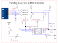
Yes - it probably does mean that, but it probably refers to the transformer between the mains and your circuit.I assumed they meant by a transformer.
To me it sounds like a complicated way of going about it. It you want to regulate the current, make a constant-current circuit!"test" pulse of a set DC voltage every few seconds to check the skin resistance?


")


