MCU Controlled BJT NPN Switch

Thread Starter

Z'YonG

Joined Feb 2, 2017
63
I need a switch that can be controlled by MCU to switch on and off the whole circuit board.

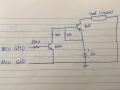
I am using a BC547 NPN BJT as the switch, and connected my circuit as below:

upload_2018-7-4_10-39-16.png

When I construct the connection, I noticed that, when I connected the collector and emitter terminal with the diagram show above, the base will have a voltage of -4.4V showed on the multimeter (that is with the multimeter: negative connected with ground of the circuit, and positive on base terminal).

The circuit works when I use the power supply to supply voltage to the base terminal, the switch is on when Vbase > 0.7V, and off when Vbase < 0.7V.

However, when I use the MCU GPIO to supply the voltage to the base terminal of the BJT, no matter whether I turned on or off the GPIO pin (3.1V when on, and 10mv when off), the switch is always on.

I have also tried PNP with connection as below, but it is always on no matter whether I connected the base terminal with power supply or MCU GPIO pin.

upload_2018-7-4_11-13-57.png

I am trying to identify the problem and find a solution for this. Any help will be great. Thanks in advance.
 

dl324

Joined Mar 30, 2015
18,326
When I construct the connection, I noticed that, when I connected the collector and emitter terminal with the diagram show above, the base will have a voltage of -4.4V showed on the multimeter (that is with the multimeter: negative connected with ground of the circuit, and positive on base terminal).
You can't have a negative voltage without a negative supply unless you have the leads on the meter reversed. Double check what you're doing.
The circuit works when I use the power supply to supply voltage to the base terminal, the switch is on when Vbase > 0.7V, and off when Vbase < 0.7V.

However, when I use the MCU GPIO to supply the voltage to the base terminal of the BJT, no matter whether I turned on or off the GPIO pin (3.1V when on, and 10mv when off), the switch is always on.
What is the load? Do the experiment again and measure the voltage on both sides of the base resistor (with respect to ground) and the collector voltage.
 

Thread Starter

Z'YonG

Joined Feb 2, 2017
63
For the BJT NPN Switch, using power supply for base terminal, the base emitter voltage Vbe is about 300mV, but with the MCU, the Vbe is about 0.7V, which is enough to turn on the switch. However, I am not sure why it is doing things like that.
 

Thread Starter

Z'YonG

Joined Feb 2, 2017
63
What is the load?
Do the experiment again and measure the voltage on both sides of the base resistor (with respect to ground) and the collector voltage.

The voltage between collector and emitter: Vce is about 4.9V.

with power supply (0V), the voltage before and after the resistor are the same :15mV
with MCU and GPIO OFF, before connect the pin to the switch, it is about 10mV, once it is connected to the base terminal, voltage before resistor is 0.863V, after the resistor is 0.722V.

without connecting anything to the base terminal, the Vbe is about 15mV, which is the same as connect 0V from power supply.

So somehow when the MCU connected to the base terminal, the voltage got pulled up from 10mV to 0.7V, which turn on the switch.
 

Thread Starter

Z'YonG

Joined Feb 2, 2017
63
I found where the problem is. For the NPN BJT Connection, the MCU suppose to connect with the ground with battery like this:
upload_2018-7-4_14-2-7.png

However, as my MCU is on the circuit, hence the ground of the MCU is actually connected with the ground of the circuit, so my design become like this:
upload_2018-7-4_14-3-19.png

Therefore, the load is actually connected with power and ground at all time, hence always on. Silly mistake.
 

dl324

Joined Mar 30, 2015
18,326
Therefore, the load is actually connected with power and ground at all time, hence always on.
To switch power to a load that's grounded, you need to use a PNP transistor or P MOSFET. This is referred to as high side switching.
 

ScottWang

Joined Aug 23, 2012
7,501
How much current does the load needed and what is the load?
How much current does the battery could provides?
Which Mcu do you used and the operation frequency of load?
 

DickCappels

Joined Aug 21, 2008
10,661
In the case of the PNP that won't turn off it might be because the emitter is always about a volt higher than the MCU V+ (about 5V), that would mean that base current always flows through the 680 ohm resistor, keeping the transistor on. You can probably remedy this by putting two or three 1N914 or similar diodes in series with the PNP base.

You would do well to answer Scott's question in post #7 above. It would be good to know how to assure the transistors are in saturation and the current ratings not be exceeded, if I am reading his mind correctly :) .
 

ScottWang

Joined Aug 23, 2012
7,501
In the case of the PNP that won't turn off it might be because the emitter is always about a volt higher than the MCU V+ (about 5V), that would mean that base current always flows through the 680 ohm resistor, keeping the transistor on. You can probably remedy this by putting two or three 1N914 or similar diodes in series with the PNP base.

You would do well to answer Scott's question in post #7 above. It would be good to know how to assure the transistors are in saturation and the current ratings not be exceeded, if I am reading his mind correctly :) .
To avoid too many guess, probably, maybe.
 

Thread Starter

Z'YonG

Joined Feb 2, 2017
63
Hi all, Thanks for all your help. I did some research last night and designed a switch with NPN and PNP, and yes, the PNP switch that I got early that always turned on is because the voltage from my MCU is far less than the supply voltage of the circuit. My MCU can only supply 3V from its GPIO pin, and the supply voltage for the whole circuit is 6V. the current that I need for the circuit is about 30mA. Below is the switch that I designed with BC547 (NPN) and BC327 (PNP), and it works.
 

Attachments

dl324

Joined Mar 30, 2015
18,326
Below is the switch that I designed with BC547 (NPN) and BC327 (PNP), and it works.
Glad you have it working.

This is your circuit drawn more conventionally:
upload_2018-7-4_19-17-58.png
If RL needs 30mA, R3 can be larger. Q1 is going to draw about 3mA from your GPIO; you could decrease that by a factor of 10.

EDIT:
You could use a single logic level P MOSFET, but you'd need to use a level shifter or determine how much current you can safely force into the GPIO when it's HIGH. I've used an LED in place of the two diodes @DickCappels mentioned earlier.
 
Last edited:

DickCappels

Joined Aug 21, 2008
10,661
I am impressed! What you solved is very similar to an interview question that some (unsuccessful) candidates for engineering positions were not able to solve.
 
Top