Facebook
 Google
 GitHub
 Linkedin
MaxHeadRoom
- Joined Jul 18, 2013
- 30,728
If the light is a steady flash, it means that the processor is receiving a command from the console.
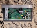
Check the 105VDC from the bridge -ve to Q1 or whatever the designation of the SCR on the HS is.
Test input and output pin before and after a command is issued.
Check the 105VDC from the bridge -ve to Q1 or whatever the designation of the SCR on the HS is.
Test input and output pin before and after a command is issued.