MC2100 treadmill motor control circuit

pagpatrice

Joined May 28, 2020
12
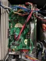
I managed to restart with two resistance 102 so 500 Ohms and an IGBT that I had but too small, suddenly I have to replace this with your avsi is what I can mount instead of IRG4PC40K an AUIRGP4063D or IRG4PC50FPbF?

the AUIRGP4063D has an internal diode is it better, right?
 

juanzelada

Joined Jun 18, 2020
1
[QUOTE = "Solo761, publicación: 1440980, miembro: 247826"]
Gracias

Q5 es APT30GT60BR
R45 y R46 están marcados 30C, que es 20k Ohm

Solo U5 sigue siendo difícil de alcanzar :RE, intenté jugar un poco con el software de manipulación de fotos para aumentar el contraste, pero no pude obtener nada legible :RE. Es demasiado pequeño con una superficie rugosa, por lo que es difícil de fotografiar.

Gracias por las fotos, intentaré buscar en Google un poco más para identificar U5, si encuentro algo, escribiré de nuevo :).
[/CITAR] Il codigo de U5 veo que es IR2127S

GOOGLE TRANSLATION:
[QUOTE = "Solo761, post: 1440980, member: 247826"]
Thank you

Q5 is APT30GT60BR
R45 and R46 are marked 30C, which is 20k Ohm

Only U5 is still hard to reach: RE, I tried messing around with photo manipulation software a bit to boost contrast, but couldn't get anything readable: RE. It is too small with a rough surface, making it difficult to photograph.

Thanks for the photos, I will try Googling a bit more to identify U5, if I find something, I will write again :).
[/quote]
The U5 code I see is IR2127S

Moderators note : Please keep ALL conversations in English.
Turn OFF your auto translate of your browser.
 
Last edited by a moderator:
Hi,
I would like to contribute to this excellent site my reverse engineered information for the MC2100ELS-18W controller card. I was asked to "repair" a treadmill which had this card. The first problem was the shorted control "transistor" IRG4PC. This was locally available but on replacing there was a flash-over along the glue for the paper label which took out the micro-processor! A new card was purchased, different component lay-out but the same circuit except for an additional capacitor in series with the original connected between the 2 different system zero volts. No problems encountered with the new card although being an old school systems design engineer I do not like the control system. It appears there is no feedback when there is somebody using the treadmill, the speed varies too much for me. Yes the belt speed sensor appears to be working.
Anyway I trust somebody has a use for the information.
Any faults please advise and I will correct. There are some Zero ohm surface mount resistors which seem a little strange for me.
 

Attachments

Bhen1374

Joined Jul 11, 2020
1
Pls help me, i have nordictrack, motor not working, when i press start button, led flash 8 times then off in a second then flash 8 times again and so on
mc2100els 18w board motor controller
 
Thanks again, but I have some difficulty thinking it's the right scheme
The diagram you have shown me shows the values of the components completely different.
example
the capacitor C5 on the board is 560 micro F while the scheme is 1500
The capacitor C6 on the board is in series with the R19 68K 2W resistor while on the diagram they are in two different places
On the MOF-FET Q5 (IRFP250) the positive comes out of the SCR S4025

I believe that the pattern is not the same
I repeat it is an M2100E rev D ICON 2007 card
hello can you give more info on this caoacitors?? c2 and c5

on transportation to the new house ened up with the board like this
 

Attachments

pagpatrice

Joined May 28, 2020
12
Hi,
I have a new problem that I don't understand, after replacing R61 and R62, I replaced my IGBT with an IRGP4069DPBF and replaced the motor with a new one:
first start OK, calibration OK, after 20 min of work it slowed down and went into folds back mode.
I start the calibration again and now with the setting to the minimum it goes too fast and always after 20 min of work it goes into folds back mode.
I have looked at all of them and everything seems OK, I don't understand ...

Hi,
I would like to contribute to this excellent site my reverse engineered information for the MC2100ELS-18W controller card. I was asked to "repair" a treadmill which had this card. The first problem was the shorted control "transistor" IRG4PC. This was locally available but on replacing there was a flash-over along the glue for the paper label which took out the micro-processor! A new card was purchased, different component lay-out but the same circuit except for an additional capacitor in series with the original connected between the 2 different system zero volts. No problems encountered with the new card although being an old school systems design engineer I do not like the control system. It appears there is no feedback when there is somebody using the treadmill, the speed varies too much for me. Yes the belt speed sensor appears to be working.
Anyway I trust somebody has a use for the information.
Any faults please advise and I will correct. There are some Zero ohm surface mount resistors which seem a little strange for me.
Thanks for this work, are you sure of the values of R61 and R62 because I replaced by 2 X 1Kohms, could that be my problem?

How to suppress the current detection to lose the folds back mode?

Do you have any ideas for me ?
 
Hi,
I have a new problem that I don't understand, after replacing R61 and R62, I replaced my IGBT with an IRGP4069DPBF and replaced the motor with a new one:
first start OK, calibration OK, after 20 min of work it slowed down and went into folds back mode.
I start the calibration again and now with the setting to the minimum it goes too fast and always after 20 min of work it goes into folds back mode.
I have looked at all of them and everything seems OK, I don't understand ...


Thanks for this work, are you sure of the values of R61 and R62 because I replaced by 2 X 1Kohms, could that be my problem?

How to suppress the current detection to lose the folds back mode?

Do you have any ideas for me ?
Hi,
I rechecked my board and found that the 2 resistors R61 and R62 should be the same value, R61 looks like marking 201 but could also be 102 when read from the other direction, the same as R62, which is more logical. Measurement across them, in-situ, indicates about 98 ohm. This means that the resistors should be 2 x 200 ohm, not as stated on my components list on message #166. I have amended the list.
Regarding your current fold back problem, it “might” be because you have about 500 ohms to drive the SCR instead of 100 ohms. How do you know its gone into "fold back"mode? What is the motor current before and after this event?
It could also be detected by the driver IC 10 or from the processor which detects current in R63.
If it is going into fold-back there is a obviously a reason and removing the feed-back could cause too many other expensive problems. You should look more for the cause.
A stupid question but could the selected program be causing the change at 20 minutes? Can you immediately restart correctly and 20 minutes later it shuts down again?
I found on my replacement board that the potentiometer only adjusted the maximum speed obtainable, it did not calibrate the actual speed which should not be required. The actual speed is fed back to the display unit which should be controlling the PCM to U10 to maintain the correct speed although I found this to be a very “sloppy” system when somebody was using the treadmill.
I have attached a new components list and a photograph on my defect card showing R61/62 (I hope you can see why the confusion from the photograph)
Good luck.
 

Attachments

Hi,
I have a new problem that I don't understand, after replacing R61 and R62, I replaced my IGBT with an IRGP4069DPBF and replaced the motor with a new one:
first start OK, calibration OK, after 20 min of work it slowed down and went into folds back mode.
I start the calibration again and now with the setting to the minimum it goes too fast and always after 20 min of work it goes into folds back mode.
I have looked at all of them and everything seems OK, I don't understand ...


Thanks for this work, are you sure of the values of R61 and R62 because I replaced by 2 X 1Kohms, could that be my problem?

How to suppress the current detection to lose the folds back mode?

Do you have any ideas for me ?
Hi,


I rechecked my board and found that the 2 resistors R61 and R62 should be the same value, R61 looks like marking 201 but could also be 102 when read from the other direction, the same as R62, which is more logical. Measurement across them, in-situ, indicates about 98 ohm. This means that the resistors should be 2 x 200 ohm, not as stated on my components list on message #166. I have amended the list.
Regarding your current fold back problem, it “might” be because you have about 500 ohms to drive the SCR instead of 100 ohms.
It could also be detected by the driver IC 10 or from the processor which detects current in R63.
If it is going into fold-back there is a obviously a reason and removing the feed-back could cause too many other expensive problems. You should look more for the cause.
A stupid question but could the selected program be causing the change at 20 minutes? Can you immediately restart correctly and 20 minutes later it shuts down again?
I found on my replacement board that the potentiometer only adjusted the maximum speed obtainable, it did not calibrate the actual speed which should not be required. The actual speed is fed back to the display unit which should be controlling the PCM to U10 to maintain the correct speed although I found this to be a very “sloppy” system when somebody was using the treadmill.
I have attached a new components list and a photograph on my defect card showing R61/62 (I hope you can see why the confusion from the photograph)
Good luck.
 

Attachments

pagpatrice

Joined May 28, 2020
12
Hi,


I rechecked my board and found that the 2 resistors R61 and R62 should be the same value, R61 looks like marking 201 but could also be 102 when read from the other direction, the same as R62, which is more logical. Measurement across them, in-situ, indicates about 98 ohm. This means that the resistors should be 2 x 200 ohm, not as stated on my components list on message #166. I have amended the list.
Regarding your current fold back problem, it “might” be because you have about 500 ohms to drive the SCR instead of 100 ohms.
It could also be detected by the driver IC 10 or from the processor which detects current in R63.
If it is going into fold-back there is a obviously a reason and removing the feed-back could cause too many other expensive problems. You should look more for the cause.
A stupid question but could the selected program be causing the change at 20 minutes? Can you immediately restart correctly and 20 minutes later it shuts down again?
I found on my replacement board that the potentiometer only adjusted the maximum speed obtainable, it did not calibrate the actual speed which should not be required. The actual speed is fed back to the display unit which should be controlling the PCM to U10 to maintain the correct speed although I found this to be a very “sloppy” system when somebody was using the treadmill.
I have attached a new components list and a photograph on my defect card showing R61/62 (I hope you can see why the confusion from the photograph)
Good luck.
Regarding your current fold back problem, it “might” be because you have about 500 ohms to drive the SCR instead of 100 ohms
I wrote something stupid, it is 100Ohms that I installed


A stupid question but could the selected program be causing the change at 20 minutes? Can you immediately restart correctly and 20 minutes later it shuts down again?
no that's not it, this morning it just worked 1 min and yesterday 45 min, after folding it goes up correctly sometimes 5 min sometimes 10 min, sometimes 1 min, it's not regular...

It could also be detected by the driver IC 10 or from the processor which detects current in R63.
I think there is also an error, color brown / yellow / black / black / brown so either 140 Ohms or 1MOhms depending on the direction of reading, for me the measurement is 14KOhms ???

no-load consumption is 3 Amp and under load changes between 13 and 16 Amp nothing abnormal before the retraction, the motor is new so I don't understand
to modify the detection threshold would need to increase R63?
 

pagpatrice

Joined May 28, 2020
12
Another small error, R60 = 01C = 10kOhms on the list it is written 1kOhms.

So this evening of another test, now it stops working after 1 min or 2 and goes up to 17 AMP in load (I weigh 85kg), 4.2 Amp empty (4km / h), the carpet is well lubricated, the engine is new and the board is clean. The security is triggered between 17 and 18 Amp.
When I run, the LED sometimes blocks when my foot touches the mat as if I were too heavy (yes diet) :D
So the engine consumes more energy ... why ???
If I look at your diagram to increase the safety threshold I would have to put a variable resistance between R63 and R60, you confirm?
Hi,

You are correct with the value of R60 it should be 10K. I also unsoldered R53 to check the actual value and it is 1Meg. The colour coding is not what I remember from many years ago, Br, Bl, Gr used to be 1Meg. I also rechecked the component list and corrected R43 and R47, (copy and paste problems).
If the system is shutting down due to over-current then something is wrong. Is anything getting hot to touch?
I mentioned there could be 2 ways for protection from over-current:-
1 Pin 6 of U10, if you check the data sheet, is current protection, Cs.
2 Actual current, measured by R63, is sent to the processor (pin 4) and also could control the PWM to the drive controller (sheet 7 pin 8), U10.
If you really want to change the feedback current, this is on your own head, then a potentiometer across R63, with the wiper connected to R60, would allow you the vary the feedback.
Good luck.

I have attached a new version of the components list and corrected drawing sheet 2.
 

Attachments

pagpatrice

Joined May 28, 2020
12
Hi,

You are correct with the value of R60 it should be 10K. I also unsoldered R53 to check the actual value and it is 1Meg. The colour coding is not what I remember from many years ago, Br, Bl, Gr used to be 1Meg. I also rechecked the component list and corrected R43 and R47, (copy and paste problems).
No problem if I find another error I will tell you.
Nothing heats up.
Thank you for confirming the value of R53, I have not yet desoldered it to have the real value but there is nothing else on the circuit which could distort but if it is at 14 kOhms it could be the problem because it detects the motor voltage so will send false information.
For the modification of the protection threshold I would like to avoid but if I can not find anything else I would do a test with a VR in order to understand.
How much intensity on your motor? you know
 

Hyper10

Joined Sep 7, 2020
1
Thanks to whoever posted the schematic. I had an issue with a similar board MC5100DTS-50W (Nordic Track X9i) and it was helpful to diagnose a problem. Everything on the treadmill worked except the motor wouldn't run. It turned out that L1 was damaged (open circuit). On the MC5100DTS it doesn't use the 10V zener (D8) to generate the lower voltage DC signal. It uses a switching circuit that L1 is a part of.

Also one of the 1000uF 200V capacitors was swollen so I'm replacing that as well.
Hi quenzerj - Curious if you were able to resolve the issues with your MC5100DTS with the fixes you mentioned, and have you had any additional issues since? Nordictrack seems to be having a rash of failures on their X22i and X32i control boards, which appear to use the same motor control board. Replacement boards are being sent to customers, but are delayed many weeks. I have an x22i treadmill on the way, so I am trying to get ahead of the eight ball on this. Thanks!
 

pagpatrice

Joined May 28, 2020
12
Yesterday I checked R53 is doing well 1M Ohms unsoldered, the Fault pin of U10 remains negative so it is not this security now the motor goes up to 18Amp under load, it is as if the motor was dead when it is new...
 

IamJatinah

Joined Oct 22, 2014
136
Hi All, Nordictrack has a zoom scheduled for tomorrow on that x22/x32 issue which I found out about maybe 3 weeks back. We have since found a fix for a design issue and start proving-in things tomorrow. With the testing starting and the meeting with Nordictrack to try and stop their disaster, more info available soon. Replacement boards from nordictrack for warranty customers still have the original design from the pics I have been sent, so they are yet unaware of the mistake. There may be a motor issue going on with the x22/x32 as we've seen motor rails blown out on boards only weeks old, and the main problem, is a no-belt spin at start-up.
 
Top