MC2100 treadmill motor control circuit

Solo761

Joined Sep 10, 2014
3
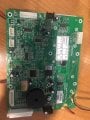
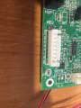
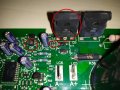
Hi, all of them are on the left side, I've attached two images with them circled. I just need confirmation about what these 4 components are exactly

U5 - MIC 4427
Q5 - APT30GT60BR
R45, R46 - resistors that so far seem to be 20k Ohm

Thanks!
 

Attachments

Solo761

Joined Sep 10, 2014
3
Thanks

Q5 is APT30GT60BR
R45 and R46 are marked 30C which is 20k Ohm

Only U5 is still elusive :D
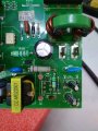
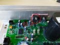
, I tried playing a bit with photo manipulation software to boost contrast but haven't managed to get anything readable :D. It's too small with rough surface so it's hard to photograph.

Thanks for the pics, I'll try googling some more to id U5, if I find something I'll write back :).
 

gomerjs

Joined Dec 11, 2019
12
1.jpg
Hi friends I use a translator, I apologize. MC2100E REV A Board There is no power to the electric motor, everything else works. The engine runs on an external power source well. The element Q5 was replaced, the tracks were restored. Power on the LG6 and LG5 did not appear. He is not there completely. Helping to solve the problem, no one can fix the controller here.
 

Attachments

MaxHeadRoom

Joined Jul 18, 2013
28,619
First, are you trouble shooting it on a T.M. or as a second purpose?
LED LD1 should light steady when powered up, when a PWM control signal is seen into 8 pin socket HD2, the LED should flash steady.
Max.
 

MaxHeadRoom

Joined Jul 18, 2013
28,619
I meant what is happening with the status LED?
And is the board being used on a treadmill or a second use such as a machine tool etc?
Max.
 
Good morning,

I have a Proform Quick 7.0 treadmill that mounts an MC2100E rev D card that has obviously been tampered with and I believe that the components that have been mounted are incorrect.
Could someone give me the circuit wiring diagram

Thank you
 

MaxHeadRoom

Joined Jul 18, 2013
28,619
Do a search here (MC2100) and it will reveal previously posted reverse engineered schematics.
Are you using it in the original T.M. or as aux usage?
Max.
 
Do a search here (MC2100) and it will reveal previously posted reverse engineered schematics.
Are you using it in the original T.M. or as aux usage?
Max.
thank you for answering
I've already done a lot of research but I can't find the rev d scheme
what do you mean "Are you using it in the original T.M. or as aux usage?"
The card is mounted on a treadmill that they tried to repair with a MOS-FET installed, while I thought I understood that the rev D mounts an IGBT, is it true?
I just wish I could understand where to start

Thank you in advance
 
Post #31 https://forum.allaboutcircuits.com/...or-control-circuit.100678/page-2#post-1267375
Also other posts here.
I meant is the board still in the treadmill or being used for other purposes?
Max.
Thanks again, but I have some difficulty thinking it's the right scheme
The diagram you have shown me shows the values of the components completely different.
example
the capacitor C5 on the board is 560 micro F while the scheme is 1500
The capacitor C6 on the board is in series with the R19 68K 2W resistor while on the diagram they are in two different places
On the MOF-FET Q5 (IRFP250) the positive comes out of the SCR S4025

I believe that the pattern is not the same
I repeat it is an M2100E rev D ICON 2007 card
 

MaxHeadRoom

Joined Jul 18, 2013
28,619
Unfortunately there are a few versions of the MC2100, although many use the same power devices and the 20hz pwm for the control input.
Never seen one with a mix of Mosfet (motor PWM) and SCR (SCR bridge) though ?
The early MC-60 used the SCR's for AC phase control.
Does it look like post #64?
Max.
 

gomerjs

Joined Dec 11, 2019
12
the diode LD1 is off, nothing happens when you select a program.
I understand that there is no signal from the PWM controller in the connector HD2
He removed the top board, how to check the PWM functionality?
There is only a multimeter
 

Attachments

MaxHeadRoom

Joined Jul 18, 2013
28,619
Typically the LED is off after switch on, after a second or two the LED comes on steady, indicating it is ready, once it receives a command, it flashes at a steady rate.
It could be the low voltage power supply check the output of the 7805 regulator.
Max.
 
Unfortunately there are a few versions of the MC2100, although many use the same power devices and the 20hz pwm for the control input.
Never seen one with a mix of Mosfet (motor PWM) and SCR (SCR bridge) though ?
The early MC-60 used the SCR's for AC phase control.
Does it look like post #64?
Max.
can anyone tell me how to find the correct wiring diagram? for example can you indicate the manufacturer of the card?
 

MaxHeadRoom

Joined Jul 18, 2013
28,619
can anyone tell me how to find the correct wiring diagram? for example can you indicate the manufacturer of the card?
Wouldn't swear to it, but I suspect the same Co that makes many of the T.M. motors, i.e. Johnson (Chinese) is the Manuf.
The only schematics I have come across are the ones posted previously here.
Max.
 
Top