MC-60 Motor Controller Repair (Treadmill)

n1ist

Joined Mar 8, 2009
189
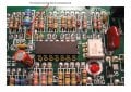
Looking at the schematic (there's a link to it in the first post), this board is NOT isolated from the AC mains. Be real careful when working on it, and DO NOT use any instruments (meters, scopes, PC soundcard scopes) that plug in to the wall or are not double-insulated without powering this board from an isolation transformer.
/mike
 

tom66

Joined May 9, 2009
2,595
It looks optoisolated - the optocoupler controls the SCRs. But still, I wouldn't want to risk it.

EDIT: Take that back, the +12V supply is definitely not isolated. But then, why is there an optocoupler?
 

Thread Starter

thearrow

Joined Aug 24, 2010
24
Any last guesses for some components I can replace in hopes of fixing this thing?

Soon I feel like I'm going to give up and order a replacement board either here or here. It's cheaper than blowing a few hundred on a new treadmill.
 

tom66

Joined May 9, 2009
2,595
The only thing I could think of would be water damage of any kind. The way that non-isolated power supply is designed could have put mains voltage on one of the chips and released the smoke. You might not even notice it; look carefully at the ICs for damage. If one of them is damaged, it is a simple replacement. But this would have to be quite unlucky.

Also, I think the RPS1 and RPS2 resistors are suspect. You mentioned that you were touching them up and that after this the CUR LIM problem occurred. Can we get a better look? I would try resoldering them and checking the traces are ok.
 

Thread Starter

thearrow

Joined Aug 24, 2010
24
My crappy messy soldering jobs could be the culprit? :D

RPS 1:


RPS 2:


I can't see any obvious damage on the ICs, should I bother replacing them, or is it more likely the traces on the board that are shot?
 

tom66

Joined May 9, 2009
2,595
Check for continuity (use your multimeter on the ohms setting or on the continuity setting) between the terminals of the resistors and the bottom of the board where the resistors are. If you don't get continuity break out your iron and try again.
 

Thread Starter

thearrow

Joined Aug 24, 2010
24
One probe on the top of the board at the end of the resistor and one probe underneath the board where the resistor sticks out? Check.

I have continuity on both ends of both resistors.


Also, an update:

Testing the SCRs with Joe's method on the previous page, on this step:
Place the negative lead on the cathode and the positive lead on the anode. Jumper the positive lead to the gate and the voltage should read approx .7 V for silicon devices (some meters might read approximately 700 - mine read 632 or 0.632V). Maintain the Anode and Cathode connection and disconnect the gate lead. The reading should remain close to the previously observed number.

As soon as the positive lead is jumped to the gate it reads close to .64V, but then rapidly decreases to nothing over a period of about a second, even if the jump is maintained...... Could this be a sign that the SCRs are bad?
 
Last edited:

JoeJester

Joined Apr 26, 2005
4,390
As soon as the positive lead is jumped to the gate it reads close to .64V, but then rapidly decreases to nothing over a period of about a second, even if the jump is maintained...... Could this be a sign that the SCRs are bad?
Normal SCRs are switched on and remain on until the anode and cathode are the same potential. Under your test setup, I would expect the SCR to turn on and remain on. If yours exhibit a behavior other than that ... I would replace the SCRs.

Now the important part. If you didn't test the SCRs out of circuit, your readings (assuming your decreasing to nothing means it went to the overload or open) you could be influenced by the other circuit components. If you tested them out of the circuit ... desoldered from the board, then I would replace them.
 

tom66

Joined May 9, 2009
2,595
When testing SCRs, you have to be careful that it is not your meter causing the effect. Most meters supply about 1mA to 5mA on the diode test range - for some SCRs, this isn't enough holding current (that is, the current required to keep the SCR on.) Also, the slow decay to zero can also be explained: if you connect a diode to the terminals, and then disconnect it, the reading will not drop to zero instantly, because the meter's sampling cap (nor its ADC) doesn't drop to zero instantly. Usually, it will decrease to zero within a second, this is common of most (but not all) meters.
 

Thread Starter

thearrow

Joined Aug 24, 2010
24
Ok, so the decreasing voltage was probably due to the other components in the circuit, since I tested them in-place. So I'm assuming if I test them out of the circuit they'll just hold the normal reading...

Should I just go ahead and get replacements for the SCRs and the ICs and just replace all of them anyway?
 

tom66

Joined May 9, 2009
2,595
It is probably the best bet you have. Since it doesn't seem like anything else could be wrong. In the pictures, what are those white marks (on the boards and ICs?)
 

Thread Starter

thearrow

Joined Aug 24, 2010
24
In which pictures? The first ones had a bunch of residue from a label, I cleaned it off for the other pics of the ICs.

I just went ahead and placed an order for a bunch of components:

2x LM324N
1x MOC3052
2x S4020L
2x Replacement RPS 1 resistors
2x Replacement RPS 2 resistors

Hopefully a combination of replacements will fix it, if not I can always get a replacement board. Any advice for removing the big 14DIP ICs?
 

tom66

Joined May 9, 2009
2,595
Since you don't care about damaging the old ICs, apply heat to each pin from any soldering iron and use a solder sucker, like the one below, to remove the solder. Then use a small flathead screwdriver to lift the IC out.


This is the method I use and it seems to work well.

It takes some practice to get the sucker to work properly (you have to arm it first, apply heat, then suck the solder out before it solidifies.) Be careful not to lift any traces or you'll have more problems.
 

Thread Starter

thearrow

Joined Aug 24, 2010
24
Well, this sucks.

I've replaced the 2x 14pin ICs, 1x 6pin IC, and both RPS 1 and RPS 2 resistors.

I've checked continuity on both sides of the resistors, each pin of the ICs.
I've tested each old resistor and each new resistor and the resistances match.

I plug everything in and get nothing but the +12V light. (No SPD CNTL or SCR TRIG LEDS) and obviously, no power to the motor.
This means I screwed something up.......?

Here's a bad picture, I'll get better ones soon:
 
Last edited:

Thread Starter

thearrow

Joined Aug 24, 2010
24
RPS 1 / U1:

Looks like I uncovered a little bit of the traces under U1, but they still all look intact...

RPS2 / U2 / U3 :


I know the resistors are crazy high, but whatever.
Keep in mind that while it doesn't look pretty, I've tested continuity between all of the pins and their solder pads on the underside of the board.....
 
Last edited:

Thread Starter

thearrow

Joined Aug 24, 2010
24
Touched up some stuff, got the SPD CNTL light back.

Still no SCR TRIG light or motor power.......


Edit: Just replaced both S4020L gates, made no difference. Still no SCR TRIG.

This is a more similar problem to the problems some people were having in that old thread, most resolved it by replacing the SCR TRIG LED, I wonder if that's the problem. I'll try shorting it out to test....
Shorting the SCR TRIG LED still didn't power the motor...... took out the LED and the LED lights up with a battery...

0V across R12.....
Some voltages across R2 and R3...
Some voltage across the 2M resistor above U2 (4) in the schematic...
12mV across R7...

When I touch one probe of my multimeter to R7, the CUR LIM light flashes and the motor stutters....

How can I test the 14pin ICs (U1/U2) to see if they're working?
Why doesn't the motor get power yet?!?!? It feels like I'm so close!
 
Last edited:

JoeJester

Joined Apr 26, 2005
4,390
Can you post a close up, both sides of the PCB in the R7 area? Touching it with a probe could have made positive contact with the board.

The last pictures you shown have alot of suspicious soldering connections.

As far as testing the chips, it would be better using an oscilloscope.

The poor connections are circled in yellow. One note shows what appears to be an unconnected 200k resistor.
 

Attachments

Last edited:

Thread Starter

thearrow

Joined Aug 24, 2010
24
Thanks for the feedback. Thanks for taking the time to mark up the picture.

All of the connections you circled have fresh solder underneath. Especially the big RPS 2 resistor. I checked for continuity on all of the replacements I made, so I hoped it didn't matter what they looked like. I realize I need a lot more practice soldering! :p I didn't think it made much difference whether or not there was solder on the top, too. I'll go back and retouch those places just in case.

I'll get some pictures of the board in the R7 area in a bit.

I wish I had an oscilloscope or could make one using my soundcard, but I don't want to fry anything.... :(
 
Top