Facebook
 Google
 GitHub
 Linkedin
I've been working on a HealthRider R60 (Model HCTL07120) treadmill that had been plugged into an improperly-wired outlet and, consequently, got a brief dose of 277VAC. The main fuse on the power board blew, obviously, so I replaced it. Once it was replaced, all of the controls on the treadmill started getting power, but if I tried to start the treadmill, it would only run for about half a second and then stop. I would then have to press STOP in order to try to start it again, but I get the same result.
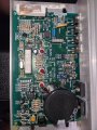
Based on the activity of the LEDs on the power and motor control boards, I'm fairly confident that the remaining issue is on the motor controller board (Model MC-2000H).
I have no formal training in electronics repair, although I do have a great deal of experience with soldering, so the effective limit of my repair ability is visual inspection and replacing clearly damaged parts.
Upon inspecting the motor control board, I found that the MOV that's located immediately after the incoming AC voltage had violently failed (half of it ended up three inches away). I painstakingly identified, researched, sourced, and ordered an equivalent replacement MOV and soldered it onto the board in place of the failed MOV.
I naively expected the treadmill to fire right up and function normally once I powered it on, but it now behaves precisely as it did before I replaced the MOV.
As I said, I lack the formal training and knowledge to know how to proceed or troubleshoot the motor controller from here, so this is mostly a shot in the dark to see if anyone might be able/willing to at least point me in the right direction.
Please excuse my ignorance and presumptuousness in even asking for help here. I've always thought that it was rude when people online just stumble into a forum of experts and ask for help with something that should be elementary to anyone with even a passing familiarity with the forum's subject, but I'm on the hook to fix this treadmill and can't afford to replace the motor controller.
Any assistance would be GREATLY appreciated.