MC 34063 need assistance for buck regulator 20v -> 12V 250mA

Thread Starter

takao21203

Joined Apr 28, 2012
3,702
I hoped so too. Parasitic oscillation you say? I use a laptop supply with long cable as well additional flywire 2m together.

Schematic is the same as from the datasheet for buck regulator, I tried 1nF and now I have 2x 1nF in series.

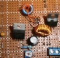
The wire coil does not cause problems- same as I bypass it or not.

I tested static load the same heat as LEDs.

I use 20K adjustable resistor between output and ground + a 2.2K resistor.

I noticed with the voltage set low, and just the 4.7K LED, the LED will actually blink, slowly as it start to light up then faster, and permanently on at some point. This is at very low voltage, very light load 4.7K only.

What could cause the parasitic oscillation? Maybe 100uF is not enough at the input or wrong type (it's a cheap new 50V).

Adding a coil could help?
 

thatoneguy

Joined Feb 19, 2009
6,359
Try running a 100 ohm resistor in series with one of the LED strings, power only that string (3 or 4), see if they act normal and the IC doesn't get hot.
 

Thread Starter

takao21203

Joined Apr 28, 2012
3,702
PDIP Package dissipation is 1.25 Watts.
Temp increases 100ºC/W after that without heatsink, since wiring is point to point, not much heat is removed by the suggested copper layer size on the board.

Even running 2W through it, let alone sourcing 4W, will cause the DIP to get hot very quickly.

The coil of wire in the sense is also an issue. Try laying the wire out in one big loop, or a bunch of lines run next to each other, going a few inches, going over a 1/4", back a few inches, and over a 1/4", then back down a few inches... glue down the ends. That will reduce size and inductance, though adding a touch of capacitance, until you can get a non-wirewound sense resistor.
It has 1uH inductance perhaps. What effect can this have on a KHz range circuit?

The point here is the dissipated power in form of switching loss.

The wire as I say does not have any effect on the heating. I don't actually use the current sensing actively, only a precaution for shorts or total runaway.

If I use a LM2576HV for LEDs from 50V at 700mA, I need a small squared heatsink and that heats up a lot if sitting on the upside. If it points upwards it's OK.

All BJT based so they have more loss than MOSFET.
 

Thread Starter

takao21203

Joined Apr 28, 2012
3,702
Try running a 100 ohm resistor in series with one of the LED strings, power only that string (3 or 4), see if they act normal and the IC doesn't get hot.
Of course it does not get hot without load current of 250mA. I explained I changed the LEDs to a static 47 Ohms load made from power resistors. Nothing changed about the heat and yes it is a bit suspiciously high. I want to try a 100oH coil as well just to see.
 

Thread Starter

takao21203

Joined Apr 28, 2012
3,702
I could add a 470uF cap. to the output, have a bag here, and they are even good for 20V input. I will try that.
 

thatoneguy

Joined Feb 19, 2009
6,359
Of course it does not get hot without load current of 250mA. I explained I changed the LEDs to a static 47 Ohms load made from power resistors. Nothing changed about the heat and yes it is a bit suspiciously high. I want to try a 100oH coil as well just to see.
Let me make the font size bigger:

PDIP Package dissipation is 1.25 Watts.
Temp increases 100ºC/W after that without heatsink


Or I use the MC34063, which takes less space, and the diode + coil can be mounted on top of the IC.

If you do not have to max out these ICs, they are very easy to work with.

Believe it or not, I have never calculated anything.
I believe it.
 

Thread Starter

takao21203

Joined Apr 28, 2012
3,702
Let me make the font size bigger:

PDIP Package dissipation is 1.25 Watts.
Temp increases 100ºC/W after that without heatsink


I believe it.
Not in a way you maybe would do calculations. But actually I did not measure the wire or look up the gauge.

I just did not understand properly that 250mA seems to be the limit for my circuit because the lack of PCB cooling.

I used this chip before but not for large currents.

I also wrote I mainly don't deal with analogue electronics. 250mA is very high current for a microcontroller circuit. Most only need 30mA or 50mA.

Especially not 250mA at 12 volts.

Sometimes I use the LM2576 as well, no direct need to use the MC34063.
 

Thread Starter

takao21203

Joined Apr 28, 2012
3,702
Filter coil tried. No effect.
470uF caps no effect.
100uH coil no effect.

Originally I wanted to power more than one LED panel with one regulator chip. Don't have 22uH coils here for the LED driver chips (which are very tiny SMD packages). No PCB either.

so maybe I will add external MOSFET, or stick with LM2576.

I want to make another grow box only with straw hat LEDs- need no cooling fans.
 

thatoneguy

Joined Feb 19, 2009
6,359
Try to see if you can get an external switch, then the heat load will be taken off the DIP, which isn't built for thermal dissipation other than by the leads.

The power should be handled by a fin heatsink without a fan on the external transistor, if the environmental temp isn't too high.
 

Thread Starter

takao21203

Joined Apr 28, 2012
3,702
A circuit I made a while ago- using a LM2576 at high voltage (the 40V type).
It works well even if the gate drive does not have a capacitor.

Fire a digital camera flash, and the core will saturate.
If the load current is high enough, the LM2576 will turn off and stay off.
That was weird actually.

As I say I did not calculate a thing, unknown cores as well.
As soon as you load it with higher currents, it may turn hot.

Just a gag circuit I have the LM2576HV here now.
 

Attachments

Thread Starter

takao21203

Joined Apr 28, 2012
3,702
Try to see if you can get an external switch, then the heat load will be taken off the DIP, which isn't built for thermal dissipation other than by the leads.

The power should be handled by a fin heatsink without a fan on the external transistor, if the environmental temp isn't too high.
Yes for 250mA, I don't even think a IRF MOSFET needs a heatsink. Or only a very small TO220 sink. I wanted to try BC327 as well and see if I can get away with it, using 2 or 3 of them. Later today.
 

tubeguy

Joined Nov 3, 2012
1,157
Please show the schematic you are using!

The 34063 running buck 20v->12v at 280mA will run nice and cool, using the datasheet circuit for the buck regulator with no external pass transistor. I think you have a parasitic oscillation type problem with that weird coil of wire in circuit!

You can even ignore the voltage regulation and set the current sense resistor value to make it act as a constant current buck driver, perfect for LEDs. So set the current sense resistor to give 0.3v at 280mA (R = V/I = 1.07 ohms).
Thanks, didn't realize this could be a CCS.:confused:
 

Thread Starter

takao21203

Joined Apr 28, 2012
3,702
One idea I have now is not to decrease voltage, but to increase it so I can use more LEDs in series. Current will be less and a heatsink or external transistor no longer needed.

I will try this with another panel.

4 in series or 8 in series- only 1/2 of the curret!

8*3=24V, so I need to boost from 19.5 to 24V, 4.5V increase.
 

Thread Starter

takao21203

Joined Apr 28, 2012
3,702
Installed 3x BC327. They heat up but not as much as the IC did.

Also the panel arythmically is decreasing a little in brightness (sometimes nothing for 20 seconds then blinking every few seconds), then quickly returning to normal. Not caused by overheating.

Weird spurious oscillation.

I want to have 4 of these panels into one box.

What I will maybe do is to build panels from red+blue LEDs, 8 in series. The red LEDs are not here yet, a good excuse to do nothing for the time being.

Also I have wired up 2x 20W white LEDs in series, and I am using a 12V -> 35V module which I patched to produce more than 60V.

A LM2596 read-made PCB is used for the cooling fans. Still have to connect the cooling fans- The LEDs work fine and illuminate the room more brightly than the fluorescent fixture.

My pineapple plant will be happy about all this.

The thin flywire cables could have a resistance of several Ohms and maybe this is causing the spurious oscillations.

I figured out the wire coil was far too much wire I could not get much brightness, until I reduced it to about 1/5.
 

Attachments

THE_RB

Joined Feb 11, 2008
5,438
You don't need an external transistor or FET!

The output switch transistor (inside the 34063) runs about 1v Vce when ON.

At your ON current of 280mA that is about 280mW dissipated in the IC when ON, which is maybe 100-200mW dissipated average, which is perfectly fine. (Regardless of Thatoneguy's massive text warning about wattage ;))

Please read my post #19 again, you need the correct value of current sense resistor which should be about 1 ohm. That sets the peak inductor current where the 34063 switches off. Please get rid of the silly "wire coil" and use the correct value of current sense resistor.

You also don't need the voltage regulation as that current sense resistor can be used to make the buck a constant current regulator.
 

Thread Starter

takao21203

Joined Apr 28, 2012
3,702
Thank you for advice about the wire coil. I have spent hours with the circuit. Today I had to shorten the wire coil. Or the brightness just would be bad.

Another idea I can not get rid off: These ICs are fake and are not capable of full current. They work, but use a much smaller die.

I paid 40 cents for these ICs.

Since when Ipeak has to be limited for a static 47R load?
 

Thread Starter

takao21203

Joined Apr 28, 2012
3,702
It is really depressing to read replies like above. As if a less than 1uH coil would have any effect on a KHz circuit.

Also it is wrong. The current limit exists to limit the output current, not to increase efficiency, or as a mandatory means.

If you regulate voltage you don't clip off the current peaks. This is science fiction.

I think from his website, RB should know much better.

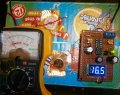
Be it- I have built a boost converter, right now only powering 5 LEDs in series. I have added a secondary trimmer for fine regulation, and it works well enough I can adjust the needle very precise to any current I want.

I also think NPN is in general not very good for a buck regulator. It works if the delta voltage is large for instance 12V to 3V, but if it is small, and the currents are large, it does not work so well. Maybe I am wrong. But I think, PNP is prefered for a buck regulator.

I know from using MOSFETs if you want to boost, you need to use NPN, and otherwise, you need a secondary rail for the gate voltage or something like that.

I also have problems with LM2576HV, the delta is only 8 volts or so at more than 30 volts input. One even runs from 50V. I can do what I want, I can not get out more than 0.7 Amps. That is what I want anyway :)

In my opinion these are allround chips, and they have limits due to their NPN BJT.

If one wanted something that does not heat up so much, a TL494 + MOSFET is used. Don't mind- I have all the components here to build some of these.

Maybe I can get away with MC34063 as booster, I hope to power 100 LEDs with one chip.
 

Attachments

cabraham

Joined Oct 29, 2011
82
The 34063 uses a pair of bjt output devices. In the buck mode, they are configured as an emitter follower. The collector to emitter forward voltage drop is typically 1.0 volt or maybe more. At 0.250 amp, that's a quarter watt of power dissipation. Multiply that by the thermal rating in deg C per watt and that figure is the temp rise of the IC.

Claude
 

Thread Starter

takao21203

Joined Apr 28, 2012
3,702
The 34063 uses a pair of bjt output devices. In the buck mode, they are configured as an emitter follower. The collector to emitter forward voltage drop is typically 1.0 volt or maybe more. At 0.250 amp, that's a quarter watt of power dissipation. Multiply that by the thermal rating in deg C per watt and that figure is the temp rise of the IC.

Claude
I made a transistor tester, coming from a programming background. So I deal with logic not so much with formula. For a PNP I measured a total 90mV dropped by the transistor.

From the MC34063 datasheet, I see the voltage can exceed 1V.

The chip became hot no matter what I tried or changed.

The TL494 is better, you can inline an Amp meter, and adjust the frequency to the point where input current is the lowest.

I have observed if it is not set correctly, the output cooler just heats up fast (in the 50W range). If it is adjusted to match the circuit, it stays relatively cool even for large currents.

Overkill for 200mA maybe. I have these chips here anyway. If I can not power 100 LEDs from one MC34063, I will build a small TL494 board.

I hope the booster works better :)

It will anyway, since I can use more LEDs per string. I also hope for better efficiency.
 

Thread Starter

takao21203

Joined Apr 28, 2012
3,702
I had the idea to build the booster when I did read the replies, so indirectly, all your replies are of some use.

Normally I don't give up so easily. I have built 7 or 8 MC34063 boards during the past few days, and fried two chips.

Also I have special LED chips here, but not the matching inductors, they need a board as well with vias and a copper plane for the heat.
 
Top