MC 34063 need assistance for buck regulator 20v -> 12V 250mA

THE_RB

Joined Feb 11, 2008
5,438
...Also it is wrong. The current limit exists to limit the output current, not to increase efficiency, or as a mandatory means.

If you regulate voltage you don't clip off the current peaks. This is science fiction.

I think from his website, RB should know much better.
...
There's no need to be rude! I know this IC quite well, I have stocked them for years for use on projects and have made many successful SMPS power supplies using this IC.

If you want to ignore my advice and keep guessing that you have "bad clone ICs" or something that's fine, but I will tell you again the current sense resistor is an important part of the circuit and needed to be properly set up to limit the peak current through the inductor, and it also affects oscillation frequency and efficiency in a big way.

If you are asking for help with an IC you might want to listen to advice from people who know the IC much better than you do. You won't be getting any more advice from me because I think your attitude stinks.
 

Thread Starter

takao21203

Joined Apr 28, 2012
3,702
There's no need to be rude! I know this IC quite well, I have stocked them for years for use on projects and have made many successful SMPS power supplies using this IC.

If you want to ignore my advice and keep guessing that you have "bad clone ICs" or something that's fine, but I will tell you again the current sense resistor is an important part of the circuit and needed to be properly set up to limit the peak current through the inductor, and it also affects oscillation frequency and efficiency in a big way.

If you are asking for help with an IC you might want to listen to advice from people who know the IC much better than you do. You won't be getting any more advice from me because I think your attitude stinks.
Hey.

For one you do not need to be subjective about my attitudes which you do not know at all.

It is not fair.

I saw your website and until today respected you as knowledgeable.

What could one say about all the details you show to the general public? I do not know, simply put. What I think it can be useful for some.

I told you I tried everything, and made 7 or 8 circuits.

I changed the wire loop actually. Because it was having so much resistance the LEDs were dim.

If the sense resistor is mandatory or not is NOT mentioned in the datasheet.

The fixed relationship between frequency and duty cycle is the problem. I think.

Again say what you want about my attitudes. What brings you to such an action? I do not know. But what I know is some 100 nH won't do anything inside such a circuit.

I do not rely to use this IC, and that's it. If I have to use resistors, I use them.

Non-inductive resistors for a KHz circuit is the same crap as 24ct gold plated, 1cm thick cables which use up 20 tons teflon for nothing.

I would like to thank you for your efforts.

One is clear- I am quite intelligible for electronics, and I make large circuits without schematics. If I can't remember, then it was not a good circuit, and I make a new one.

I don't get why you judge people so quickly just because they don't say yes and Amen to your opinion. Arrogance?

Say what you want about LEDs as well.

It is nonsense for this thread because I replaced them with a 47 Ohms resistor.

Do I HAVE TO construct a board with a big 1 Ohm resistor?
And what if it still heats up the same way?

What's your next suggestion to solve the problem?
Something about my attitudes again?

I am willing to build it with that 1 Ohms or whatever resistor, just to do you a honour for your efforts to help out.

Amen. 5 Minutes witing time.

P.S. I do not favour a man-made church it's nonsense.

Neither people who cloud themselves in such a nebula that it is almost religious. I saw a few such people on the internet already.

Actually I liked your site, but if we can not agree, I may reconsider not to have any opinion about it at all.
 

Thread Starter

takao21203

Joined Apr 28, 2012
3,702
I also use the said IC for 12V -> 3V, without a current sense, at 150 mA. Nothing heats, but with a wrong inductor, of course it heats.

So I was wondering why 12V -> 3V is regular, and 250mA heats to the margin.

Both were tried without current sense.

I also do not exclude I made a simple wiring mistake. I will build another PCB later today, clean and spaced out like the booster, and will test with 1 Ohm, and without.

Just to be on the safe side.

I will inform you of the results.
 

Thread Starter

takao21203

Joined Apr 28, 2012
3,702
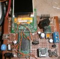
So here one of my other MC34063 applications. I use the SOIC variant here.

I think good functionality for it's 10 dollar worth of components used.

The chip does not heat abnormally at all.
I use a 50p capacitor here which gives the lowest input current.
And a modern high quality coil.

Later today we will know more. I can not exclude a wiring mistake, even if made more than one board.

I will space it out so I can know for sure, I will add a switch for wire loop and 1 Ohms resistor as well.

That is all I can do to investigate.

Normally you should only throw subjects when the other party involved is not willing to do any further work.

The case is not closed, the investigation not complete- you already give a judgement.

Believe me- not many technical documents are chinese to me. I know the basics of many technologies, even if I am not a knowledgeable expert everywhere.
 

Attachments

Top