Maximizing Output Voltage with Two Capacitors and a Battery

MrAl

Joined Jun 17, 2014
13,722
This makes no sense. How are you going to preserve any previously established charge on one of the caps if you go trying to us it as your precharge cap during the middle of this process.

Think about what happens as you bounce back and forth between Steps 2 and 3. In Step 2, you charge Cs to nearly, but not quite 2 V. Fine. But, in Step 3, you lose everything you've gained, and then some, because your large cap drains Cs nearly all the way down.

If nothing else, think about the two positive plates of your capacitors that are continuously connected together as you go between Steps 2 and 3 back and forth. There is only so much total net charge on them, so all you can accomplish is shuttling it back and forth between the two caps, and thus accomplishing nothing each cycle.
Hello again,

Did I misunderstand your procedure? That's always a possibility.
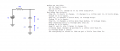
Let's see referring to my diagram with the two caps and R3 only, and with the battery E.
C1=C2/100 for example. In the diagram, CL=C2 and CS=C2/100 or something like that. CL is C-large, CS is C-small.
Charge C2 and C1 to 1v each.
Put C2 in series with E, provides us with a 2v source.
Charge C1 with that 2v source, gaining a little less than 2v on C1 and a little less on C2.
Now swap the roles of C1 and C2 such that C1+E is charging C2. That means a 3v source is charging C2, but this gets a little more complicated because C1 is so much smaller than C2.
Now we are starting with vC1=2v and vC2=2v, and the transfer starts when we connect them as above. C2 has 2v and E+C1 has 3v so we assume a small resistance in series like 1uOhm.
Now the question is, how much does C2 charge up to? Since C1 is 1/100 times C2, we can estimate for now that C2 charges up to 2.01 volts During that transfer, vC1 drops to 1.01 volts.
So we now have 1.01 volts across C1, and only 2.01 volts across C2, but 2.01v is still an increase and so is still worth looking into.
The question now becomes, how do we increase the voltage across C2 even more?
We repeat the process? This is where it gets funny.
If we swap the caps again, we now have C2 in series with E again, and C1 being charged from their sum voltage 1+2.01 = 3.01 volts.
Next C1 charges up to about 2.99 volts. C2 discharges to about 1.99 volts.
Now rearranging them, E+1.99+2.99=5.98 volts.
Using the formula I gave:
Vmax=(-(B+1)^m+(A+1)^n*(3*(A+1)^m-2)-A^3+1)/((A+1)^n*(B+1)^m)
and with A=100 and B=A and n=2 and m=2 we get:
vC1=2.990096 volts to that many digits, which should be a better approximation to the above 2.99 volts.
This seems to happen fast enough to not worry about too many iterations, and this suggests making m=n and of course B=A to get:
Vmax=-3/(A+1)^n-A^3/(A+1)^(2*n)+1/(A+1)^(2*n)+3
That's the voltage across the small cap in the end, and this clearly shows that the limiting value with n large is 3.
If this does not sound right, then you probably have to show a little more in your explanations. I would suggest using the 1,2,3,4 diagram I made to start with, and show the voltages after each transfer and how the caps are connected in each step. That will nail it.

I'll reply to the other post you made next but it's going to take a little while there's a lot in that post.
 

MrAl

Joined Jun 17, 2014
13,722
Where did this formula come from?
In your recurrence relationship it seems you have to do each transfer one by one. If you take it one step further, you get a relationship like my formula, which calculates the *final* value without having to go through each step one at a time. Note there is no voltages in my formula. That's because they can be implied by the method itself so they do not need to be calculated one at a time. It's like a series convergence formula where we no longer have to show the series. We kind of get rid of the kernel and go right to the final value.

Why have different parameters for the number of pumps since one transfer has to be followed by the other?
I allowed for variations in technique, but if we make m=n we get a simpler expression where we do them in the same order (and of course B=A which also then simplifies it further).

I'm assuming you are talking about the switching protocol that I described and that you responded to. If you are talking about some other protocol, it would be nice if you said so and defined it.
It's the same but allows for some variations.

In the protocol as I described, the amount of charge transferred at a given cycle is dependent on the voltage achieved at the prior cycle and the ratio of the capacitors. That gives us the voltage at the end of the current cycle, which in turn gives us a recurrence relationship.
Yes I gathered that. I just went one step further and calculated what happens if you do that over and over again, more or less, then simplify the results. This allows us to specify what cycle result we want to look at without going through all the ones before that. I hope I got it right though.


THIS NEXT PART HAS TO BE EXPANDED TO SEE THE PURE TEXT VERSION:
That relationship is:

\(
V_2(n) = V_2(n-1) \frac{\beta}{\beta + 1} \; + \; 2V_0 \frac{1}{\beta + 1}
\)

where

\(
\beta \; = \; \frac{C_2}{C_1}
\)

[added the following to the quote]
'tex' does not show up well in a quote, so here is the pure text version of that above:
V2(n)=V2(n-1)*B/(B+1)+2*V0/(B+1)
where
B=C2/C1

If needed, I can walk through how that recurrence relation is derived.
I could show how to take it one step farther, but it does get pretty hairy so it might be hard to outline the entire procedure. I can give a rough outline though because it's basically a series when you apply the next voltage level(s) to the next step symbolically and then you get the final value for any number of cycles all in one shot in the simplification. I can show a simpler example though.


If ß = 1000, then V2 gets to 1.5Vo (i.e., halfway from Vo to 2Vo) after 694 cycles. This is therefore the "half life" analog and is how many cycles are required to get half of the remaining distance to the asymptotic final value. To get to 1% of the final value (i.e. 1.98·Vo) takes 3914 cycles. To get to within 0.1% takes 6218 cycles.
Not sure I follow this since C1 is so much smaller than C2.


...with reference to swapping caps before or during the transfers...

Huh? Could you please explain what you mean by this?
If we run through the whole thing with C1=1 and C2=100 for example, that's that.
If we swap early, then C1=100 and C2=1.
If we swap during, then we make C1=1 and C2=100, and for the next half cycle we make C1=100 and C2=1.
C1 and C2 refer to the top drawing I made with the differential equations image. If we swap, it only means we exchange the values. This makes it possible to use the same schematic and the same equations to calculate anything we need to for any cycle(s). We don't have to make a new schematic and go through the development of the equations and solutions again.
I should probably show the derivation because it's so simple, but the drawings make it seem very complicated.

Resistance has nothing to do with how many cycles, merely with how much time each cycle takes.
Agreed.

If we are talking about the switching protocol I described, it's because the increase in complexity outweighs the benefit from just using a traditional multi-stage charge pump.
Well it's not really that difficult it's just a matter of working out the switching matrix/procedure, so any IC would just have a different switching scheme. Maybe it's hard to get a low enough resistance in the switches I don't know, because there could be more switches in series with each other in order to get the right switching to occur. Still it seems to be worth it because there are situations that don't need much current, just a higher voltage.

If it's because of some different switching protocol that you seem to have in mind, it's probably because it doesn't work at all.
Not sure what you mean here. Doesn't the drawing with the 1,2,3,4 steps outline the entire procedure?

And then...
This could be something new in the world of electronics, but I think we need a more solid proof before we apply for any patents or whatever. A working real life prototype would be really good.
 
Last edited:

MrAl

Joined Jun 17, 2014
13,722
@WBahn

I reviewed your procedure, let's see if we both are now both thinking of the same thing...

The attachment shows the circuit and procedure. Note C2 has to be flipped relative to the schematic polarity marking. That's the only reason for stating that it gets 'flipped'.
I have to recheck the closed form solution.
 

Attachments

Last edited:

MrAl

Joined Jun 17, 2014
13,722
Hello again,

If that was the correct procedure then I was able to work out the closed form solution straight up from the ODE's and the limiting voltage of C1 does come out to 2v.
This seems to be a reasonable proof of getting up to 6 volts because C1 is large and that means in series with the battery it can charge C2 up fast to 3v (after swapping C1 and C2).
See attachment.

There might be a tradeoff coming next because if we make C2 very small it takes a lot of pumps t get C1 up to 2v, but then C2 charges up fast and high.
If C2 is moderately small, it may take less pumps to get to 2v, but then we would not see the full benefit when we flip and charge C2.
This suggests an optimization process could come next to pick the best value for A and the number of pumps, or it may be application specific.

There is still the question of why we haven't seen this implemented before this, and what happens in a real-life breadboard prototype.

This is if the procedure follows @WBahn correctly.
 

Attachments

MrAl

Joined Jun 17, 2014
13,722
Hello again,

Ok one more reply after a little reflection on what we are attempting :)

There might be a problem with all of this.

That is, we are assuming that when we pump up and then connect in series that the resulting voltage is going to exist forever. However, with any load it is going to sink fast because of the small cap. That means we have to reiterate the pumping process and ending series connection. That in turn requires that we disconnect the load. That's a big problem. We would need at least some extra capacitance to keep the output from going to zero or very low.
Could this be the reason we don't see this in the industry yet? Could there be a solution?
There may be the possibility of using an even smaller cap to hold the output higher while we repump and reconnect, but this does mean adding another capacitor bringing the total up to 3 caps instead of 2.

Perhaps somebody can figure something out here to solve this.
 

MrAl

Joined Jun 17, 2014
13,722
Hello again :)

As it turns out, there is one specific application I can think of offhand where this could be useful. That is, in LED driving where we need maybe 5v from 1.2 volts. In this app, we allow pulsing the LED which gives us some light which may be used for a flashlight (very small footprint driver) or just an LED indicator that has to run from a low voltage like 1.2v or something.

Of course, there's always the possibility of some medical application that could benefit that would not need inductors which can be sensitive to magnetic fields.
Low energy applications have been popping up over the last 10 years or so.

The possibilities seem to be there.
 

WBahn

Joined Mar 31, 2012
32,940
Hello again,

If that was the correct procedure then I was able to work out the closed form solution straight up from the ODE's and the limiting voltage of C1 does come out to 2v.
This seems to be a reasonable proof of getting up to 6 volts because C1 is large and that means in series with the battery it can charge C2 up fast to 3v (after swapping C1 and C2).
See attachment.

There might be a tradeoff coming next because if we make C2 very small it takes a lot of pumps t get C1 up to 2v, but then C2 charges up fast and high.
If C2 is moderately small, it may take less pumps to get to 2v, but then we would not see the full benefit when we flip and charge C2.
This suggests an optimization process could come next to pick the best value for A and the number of pumps, or it may be application specific.

There is still the question of why we haven't seen this implemented before this, and what happens in a real-life breadboard prototype.

This is if the procedure follows @WBahn correctly.
I don't think your description agrees with your illustration. You say that C1 and C2 are both initially charged to E.

Okay.

Then you say, "Now using the circuit" and the circuit shows C1 and C2 connected so that V1 and V2 add, meaning that the initial voltage at the top of C2 would be 2E, which would result in both capacitors discharging as the battery sinks current to bring the voltage on that node down to just E. C2 would be almost entirely depleted while C1 would drop just a bit.

I think you meant to flip C2 BEFORE using the circuit -- which is then exactly the configuration that I showed (without R3, since that has no impact on final states and becomes a distractor).

Now, let's consider your closed-form pumping solution for C1, in which I'm assuming that A = the ratio of the capacitors, namely C1/C2. In your illustration, you said that C1 = 100*C2, making A=100.

1754184913869.png
You stated before, in a response to my assertion that we would need far more than a thousand cycles to get the voltage on the pumped capacitor up to within 0.1% of twice the supply voltage with a capacitance ratio of 1000, that:

"Since we know we are dealing with asymptotic behavior, we don't need to do any math to know that we will need far more than thousand cycles to get to the voltage on C2 within one part in a thousand of twice the supply voltage. How many cycles follows the same math as before."

As it turns out, it looks like we don't need 1000 cycles. It could be much fewer.
This looks like the right formula:
Vmax=(-(B+1)^m+(A+1)^n*(3*(A+1)^m-2)-A^3+1)/((A+1)^n*(B+1)^m)

where
B=A and
n is the number of pumps of the first transfer, and
m is the number of pumps of the second transfer (to the smaller cap).
B must equal A because they are both the ratio of the large cap to the smaller cap. The reason for B is to keep the expression from defaulting to a stranger appearance in the software.
This seem to show that the limit is 3v as expected (before any further additions).

So the key is in the swapping of the caps after they are charged to some level, not before.
The result seems to follow with A=2 also and not that many cycles. This is most likely because we assume that there is no resistance to slow down the charging. In real life we would have that.
Now we just have to figure out why we don't see this being used in IC chips. It might also be because the current draw would have to be very tiny. Still, it seems it could be practical for some apps. The switching technique would be more complicated, but who cares about that when we are after a higher voltage, some way, some how.
With A=100, how many cycles would it take to get C1 to within 1% of 2E? Doing the math, it turns out to be 393 cycles.

If A = 1000 and we are trying to get to within 0.1%, per the prior discussion, it turns out to be 6218, per YOUR equation.

How does that compare to my result based directly on the recurrence relation shown here: I got 6218 cycles.

The key thing to keep in mind, and that I think you are overlooking, is that the goal isn't to get C1 as close to 2E as quickly as possible. That is achieved by making the pumped capacitance much smaller than the pumper (i.e., make A << 1).

Imagine that C1 (in your latest diagram) is 1/1000 of C2. When C2 is stacked on top of the battery, it will charge C2 to within a fraction of a percent of 2E while losing only a fraction of a percent of its own voltage. When we then stack all three, we are now just a fraction of a percent from 4 V and we did it in just one cycle.

But that's not our goal -- our goal is to get the maximum total voltage that we can, which is asymptotically limited to 6E. To approach 6E, we need to use a large capacitance ratio and accept that it will take more cycles to get there.

The reason, which you didn't even attempt to consider quantitatively, is that the last step is to charge the pumping capacitor from 1E to nearly 3E by using the charge previously stored on the pumped capacitor after stacking it onto the battery. In doing so, we need to make a ~2 V swing on one capacitor while having minimal drop on the other, which means that we need the other capacitor to be very large compared to the first one.
 

MrAl

Joined Jun 17, 2014
13,722
I don't think your description agrees with your illustration. You say that C1 and C2 are both initially charged to E.

Okay.

Then you say, "Now using the circuit" and the circuit shows C1 and C2 connected so that V1 and V2 add, meaning that the initial voltage at the top of C2 would be 2E, which would result in both capacitors discharging as the battery sinks current to bring the voltage on that node down to just E. C2 would be almost entirely depleted while C1 would drop just a bit.

I think you meant to flip C2 BEFORE using the circuit -- which is then exactly the configuration that I showed (without R3, since that has no impact on final states and becomes a distractor).

Now, let's consider your closed-form pumping solution for C1, in which I'm assuming that A = the ratio of the capacitors, namely C1/C2. In your illustration, you said that C1 = 100*C2, making A=100.

View attachment 353526
You stated before, in a response to my assertion that we would need far more than a thousand cycles to get the voltage on the pumped capacitor up to within 0.1% of twice the supply voltage with a capacitance ratio of 1000, that:


With A=100, how many cycles would it take to get C1 to within 1% of 2E? Doing the math, it turns out to be 393 cycles.

If A = 1000 and we are trying to get to within 0.1%, per the prior discussion, it turns out to be 6218, per YOUR equation.

How does that compare to my result based directly on the recurrence relation shown here: I got 6218 cycles.

The key thing to keep in mind, and that I think you are overlooking, is that the goal isn't to get C1 as close to 2E as quickly as possible. That is achieved by making the pumped capacitance much smaller than the pumper (i.e., make A << 1).

Imagine that C1 (in your latest diagram) is 1/1000 of C2. When C2 is stacked on top of the battery, it will charge C2 to within a fraction of a percent of 2E while losing only a fraction of a percent of its own voltage. When we then stack all three, we are now just a fraction of a percent from 4 V and we did it in just one cycle.

But that's not our goal -- our goal is to get the maximum total voltage that we can, which is asymptotically limited to 6E. To approach 6E, we need to use a large capacitance ratio and accept that it will take more cycles to get there.

The reason, which you didn't even attempt to consider quantitatively, is that the last step is to charge the pumping capacitor from 1E to nearly 3E by using the charge previously stored on the pumped capacitor after stacking it onto the battery. In doing so, we need to make a ~2 V swing on one capacitor while having minimal drop on the other, which means that we need the other capacitor to be very large compared to the first one.
Hi,

I am not sure I follow all that you are saying here. That's because for one, you seem to be using the older formula "Vmax" which was for a completely different arrangement that I thought you already acknowledged. I've abandoned that one because that was too far from what you were doing.

The new one, "vC1max", is the current formula and that did not need to show the entire 6v because it was to see the voltage BEFORE the final stacking. The number of pumps gleaned from that formula comes out to 463 (rounded) to get to 1.99 volts, which I had deemed close enough to 2.00 for the discussion.
All I did was take the part that zeros out with large 'n':
(A/(1+A))^n
and still assuming E=1v, equate that to some small fractional percentage:
(A/(1+A))^n=fpc*2
and solve for 'n', giving me:
n=log(fpc*2)/log(A/(A+1))
or if we prefer:
n=(log(pc)+log(2))/(log(A)-log(A+1))
and setting fpc=0.005 and A=100 we get (1/2 percent error):
n=462.82 (rounded to that many digits)
If we set fpc=0.01, we get:
n=393.16 (rounded to that many digits)

The result using n=463 matched a pure time domain solution built from the network equations in the time domain and iterating 463 times which gave 1.990018313v which is about 0.5 percent lower.
The result using n=393 provided a result of 1.979969117v which is about 1 percent lower.

After that I assume that we know that with a large cap and battery connected to a very small cap the very small cap would charge up close to 3v and the large cap would not loose much voltage so we would get a result close to 6v.

The time domain solutions came out fairly simple. The precision used for the iterations was only about 16 digits but it looks good. I did not yet work out the time domain final value from the time domain expressions, but it's not too hard to do using the frequency domain equations where the error (from the perfect 2v) was stated as -[A/(1+A)]^n and that looks exact.

It may interest you to know what your recurrence relation:
V2(n)=V2(n-1)*B/(B+1)+2*V0/(B+1)
which in order to not confuse V2(n-1) with V2*(n-1) I take is the same as:
V2[n]=V2[n-1]*B/(B+1)+2*V0/(B+1)
where [n] denotes a subscript (and note here V2[n] is not the FINAL value with some 'n' it's the NEXT value given V2[n-1]),

in the final calculation comes out to:
V2[n]=2-B^n/(B+1)^n

This is the same as the result I got when we set V0=1v and V2=1v, which are the starting conditions I mentioned.
Solving that for 'n' for the two cases we get the same results:
n=393 and n=463

If we decide not to use those starting conditions and allow starting conditions V2 and V0 on the right side then we get a little bit more complicated:
V2[n]=(B^n*(V2-2*V0))/(B+1)^n+2*V0

or if we define the error as before:
err=B^n/(B+1)^n
or just
err=(B/(B+1))^n
then the final V2 from the starting V2 and starting V0 on the right side, then we can write:
V2[n]=err*(V2-2*V0)+2*V0

That would be the final value given the starting conditions V2 and V0 on the right side.

Also, if V2=V0 then this simplifies to:
V2[n]=V2*(2*-(B/(B+1))^n)
which says that the original scales with the starting value of V2 when V2=V0.
 
Last edited:

tushar6969

Joined Aug 26, 2025
8
hello sir i have come across this problem and the answer to it (im posting the question) could u help me get the answer (ans is 2Vo (c1 + 3c2)/(c1+c2) Screenshot_2025-08-25-22-01-11-32_e2d5b3f32b79de1d45acd1fad96fbb0f.jpg
 

tushar6969

Joined Aug 26, 2025
8
Where did this formula come from?

Why have different parameters for the number of pumps since one transfer has to be followed by the other?

I'm assuming you are talking about the switching protocol that I described and that you responded to. If you are talking about some other protocol, it would be nice if you said so and defined it.

In the protocol as I described, the amount of charge transferred at a given cycleis dependent on the voltage achieved at the prior cycle and the ratio of the capacitors. That gives us the voltage at the end of the current cycle, which in turn gives us a recurrence relationship.

That relationship is:

\(
V_2(n) = V_2(n-1) \frac{\beta}{\beta + 1} \; + \; 2V_0 \frac{1}{\beta + 1}
\)

where

\(
\beta \; = \; \frac{C_2}{C_1}
\)

If needed, I can walk through how that recurrence relation is derived.

If ß = 1000, then V2 gets to 1.5Vo (i.e., halfway from Vo to 2Vo) after 694 cycles. This is therefore the "half life" analog and is how many cycles are required to get half of the remaining distance to the asymptotic final value. To get to 1% of the final value (i.e. 1.98·Vo) takes 3914 cycles. To get to within 0.1% takes 6218 cycles.


Huh? Could you please explain what you mean by this?


Resistance has nothing to do with how many cycles, merely with how much time each cycle takes.

Take two capacitors charged to different voltages and referred to a common ground. Connect their other ends through a resistor. The final voltage of the system is the same regardless of the value of that resistor, since charge still can't be created or destroyed and the top plates of the capacitor plus the resistor is an isolated system.


If we are talking about the switching protocol I described, it's because the increase in complexity outweighs the benefit from just using a traditional multi-stage charge pump.

If it's because of some different switching protocol that you seem to have in mind, it's probably because it doesn't work at all.
if u have charged lets say c1 to a voltage of v+ v' then why not use the charged c1 and the battery b together to charge c2 (after first process charge c2 with the battery to v again)
 

tushar6969

Joined Aug 26, 2025
8
It's a direct application of the fundamentals. In most engineering curricula, these are covered in Physics II and it is assumed that they only need to be reviewed on the first day of Circuits I.

To get the recurrence relation, simply imagine the situation after Step #n in which C2 has been working it's way up from some initial voltage (either 0 V or, if we want to get a leg up, Vo if we precharge it initially).

So the situation looks like this:

View attachment 353426

V1 = Vo
V2 = V2(n)

What is the charge on each cap at this point?

Q1 = Co·Vo
Q2 = Q2(n) = V2(n) / C2 = V2(n) / (ßCo)

Now we move C1 from its charging position to its discharging location

View attachment 353428

When we connect the two sides, some charge, ΔQ(n), is going to flow from C1 to C2 and this will continue until the voltage on both sides are equal.

The charge on C2 when this is done, which will be the charge at the beginning of the next cycle, is simply Q2(n) + ΔQ(n) and the voltage at the start of the next cycle will be

V2(n+1) = (Q2(n) + ΔQ(n)) / C2 =(Q2(n)/C2) + (ΔQ(n)/C2) = V2(n) + (ΔQ(n)/C2) = V2(n) + (ΔQ(n)/(ßCo))

So we just need to find out how much charge is transferred during step n.

The new voltage on the left is going to be

V_left = Vo + (Q1 - ΔQ(n))/C1 = Vo + (Q1/C1) - ΔQ(n)/C1 = Vo + Vo - ΔQ(n)/Co = 2Vo - ΔQ(n)/Co

The voltage on the right is going to be

V_right = (Q2(n) + ΔQ(n)) / C2 = Q2(n)/C2 + ΔQ(n)/C2 = V2(n) + ΔQ(n)/(ßCo)

Since these have to end up the same:

V2(n+1) = V_left = V_right

Starting with V_left, we have

V2(n+1) = V_left = 2Vo - ΔQ(n)/Co

ΔQ(n)/Co = 2Vo - V2(n+1)

Plugging this into the expression for V_right, we have

V2(n+1) = V_right = V2(n) + ΔQ(n)/(ßCo)

V2(n+1) = V2(n) + [ΔQ(n)/Co]/ß

V2(n+1) = V2(n) + [2Vo - V2(n+1)]/ß

V2(n+1) + V2(n+1)/ß = V2(n) + 2Vo/ß

V2(n+1)(1 + 1/ß) = V2(n) + 2Vo/ß

V2(n+1)((ß+1)/ß) = V2(n) + Vo(2/ß)

V2(n+1) = [V2(n) + Vo(2/ß)][ß/(ß+1)]

V2(n+1) = V2(n)·[ß/(ß+1)] + Vo·[2/(ß+1)]
using this the limit of v2 as n tends infinity is independent of the ratio of capacitors (the v2(infinite) is coming to be 2 Vo using ur reccurence)which is wrong in my opinion and also the book named pathfinder has the same problem and the answer is dependent on the ratio of the capacitors
 

MrAl

Joined Jun 17, 2014
13,722
hello sir i have come across this problem and the answer to it (im posting the question) could u help me get the answer (ans is 2Vo (c1 + 3c2)/(c1+c2) View attachment 354863
Hi and welcome to the forum.

Well, without any other information the max voltage is 1.5 volts!
We would need to know what else is going on, such as some switching action. Are you implying that the circuit is the same as the ones before this so that C1 and C2 are the only two capacitors, and we are transferring energy from the battery to one or both caps and then changing the connections possibly several times in order to get a higher voltage? That's what we were doing with the previous circuits.
 

tushar6969

Joined Aug 26, 2025
8
Hi and welcome to the forum.

Well, without any other information the max voltage is 1.5 volts!
We would need to know what else is going on, such as some switching action. Are you implying that the circuit is the same as the ones before this so that C1 and C2 are the only two capacitors, and we are transferring energy from the battery to one or both caps and then changing the connections possibly several times in order to get a higher voltage? That's what we were doing with the previous circuits.
yes the thing you were doing before where u keep charging one capacitor with other and then the other with the battery again and repeat , though could u give me some better contact than this like ig or anything , we could have a better conversation there.
 

tushar6969

Joined Aug 26, 2025
8
This sounds like homework. Is it?

Even if it's not, you'll learn more and better if you make your best attempt and present it, first.
first , its not homework sir it is just from a book called pathfinder i solve for extra practice . and second, i have tried this method and i genuinely think theres no other way to do it , let me explain what i did , let the capacitors be Ca and Cb ( we can decide how to choose Ca and Cb so as to maximize final voltage) now we charge both caps to Vo voltage and then, we use (Ca+ battery) to charge Cb now, Ca would be at some Va1 < Vo and Cb would be at some Vb1 > Vo , now we charge Ca to Vo again and use (Cb1 which was charged to Vb1 + battery) to charge Ca , now Ca would be at Va2 > Vb1 > Vo and Cb would be at Vb2 < Vo . now again the same , charge Cb to Vo again and use (Ca with Va2 + battery) to charge Cb to to Vb3 > Va2 > Vb1 > Vo AND Ca would be now at Va3< Va2 . now we again charge Ca to Vo and use (Cb + battery) to charge Ca again and so on . now , when i do the math behind every cycle using KVL equations ,i reach the Voltage for (2n+2)th and (2n+1)th cycle as V(2n+2) = r1 * V(2n+1) + Vo AND V(2n+1) = r2*V(2n) + Vo . ( n goes from 0 to infinite and r1 is Ca/(Ca+Cb) and r2 is Cb /(Ca+Cb) ) and when i solve further for V(infinite) it comes upto Vo* ((Ca²+2Cb²+3CaCb)/(Ca²+ Cb² + CaCb)) and now it is clearly visible that if we want to maximize this V(infinite) we use Cb as the bigger capacitor and Ca as the smaller one. but this is not the answer in the book . id appreciate ur help now
 

WBahn

Joined Mar 31, 2012
32,940
first , its not homework sir it is just from a book called pathfinder i solve for extra practice . and second, i have tried this method and i genuinely think theres no other way to do it , let me explain what i did , let the capacitors be Ca and Cb ( we can decide how to choose Ca and Cb so as to maximize final voltage) now we charge both caps to Vo voltage and then, we use (Ca+ battery) to charge Cb now, Ca would be at some Va1 < Vo and Cb would be at some Vb1 > Vo , now we charge Ca to Vo again and use (Cb1 which was charged to Vb1 + battery) to charge Ca , now Ca would be at Va2 > Vb1 > Vo and Cb would be at Vb2 < Vo . now again the same , charge Cb to Vo again and use (Ca with Va2 + battery) to charge Cb to to Vb3 > Va2 > Vb1 > Vo AND Ca would be now at Va3< Va2 . now we again charge Ca to Vo and use (Cb + battery) to charge Ca again and so on . now , when i do the math behind every cycle using KVL equations ,i reach the Voltage for (2n+2)th and (2n+1)th cycle as V(2n+2) = r1 * V(2n+1) + Vo AND V(2n+1) = r2*V(2n) + Vo . ( n goes from 0 to infinite and r1 is Ca/(Ca+Cb) and r2 is Cb /(Ca+Cb) ) and when i solve further for V(infinite) it comes upto Vo* ((Ca²+2Cb²+3CaCb)/(Ca²+ Cb² + CaCb)) and now it is clearly visible that if we want to maximize this V(infinite) we use Cb as the bigger capacitor and Ca as the smaller one. but this is not the answer in the book . id appreciate ur help now
Thank you for providing your proposed steps. Hopefully you can see that, until you did this, the statement "i genuinely think theres no other way to do it" has no meaning because you hadn't provided ANY way to do it. But now you have, so that's something we can work with.

Second, you talk about choosing Ca and Cb so as to maximize the final voltage. Be sure that you understand that the problem is not asking you to do that, merely to find an expression for the maximum voltage that can be achieved with a given Ca and Cb.

I don't have time to look at your work in detail right now. Hopefully later today. But let's sanity check the book's solution to see if it is consistent with the results from earlier in the thread, which is that you can get 6x the battery voltage if one capacitor is much, much larger than the other.

Vfinal = 2*Vo (c1 + 3c2)/(c1+c2)

In the limit that c2 >> c1, this becomes 6*Vo. So that's very reassuring.

But, in the limit that c1 >> c2, this reduces to just 2*Vo. However, we know we can always get at least 3*Vo by simply charging both capacitors to Vo and then rearranging them in series with the battery. So there is an issue with their offered solution. Now, I'm pretty sure I know what it is, which is that it is the solution for the voltage using a particular switching algorithm, and doesn't recognize that, at some point, a different algorithm produces a higher final voltage.
 

tushar6969

Joined Aug 26, 2025
8
Thank you for providing your proposed steps. Hopefully you can see that, until you did this, the statement "i genuinely think theres no other way to do it" has no meaning because you hadn't provided ANY way to do it. But now you have, so that's something we can work with.

Second, you talk about choosing Ca and Cb so as to maximize the final voltage. Be sure that you understand that the problem is not asking you to do that, merely to find an expression for the maximum voltage that can be achieved with a given Ca and Cb.

I don't have time to look at your work in detail right now. Hopefully later today. But let's sanity check the book's solution to see if it is consistent with the results from earlier in the thread, which is that you can get 6x the battery voltage if one capacitor is much, much larger than the other.

Vfinal = 2*Vo (c1 + 3c2)/(c1+c2)

In the limit that c2 >> c1, this becomes 6*Vo. So that's very reassuring.

But, in the limit that c1 >> c2, this reduces to just 2*Vo. However, we know we can always get at least 3*Vo by simply charging both capacitors to Vo and then rearranging them in series with the battery. So there is an issue with their offered solution. Now, I'm pretty sure I know what it is, which is that it is the solution for the voltage using a particular switching algorithm, and doesn't recognize that, at some point, a different algorithm produces a higher final voltage.
thank you for trying to help me . now when i say we can choose Ca and Cb i mean to not say that we take any random values for their capacitance, i mean to say that: look , there are two capacitors they have provided in question(c1 , c2) ,now i was not sure whether to use c1 to charge c2 first or c2 to charge c1 first , that is why is assumed the one we use with the battery to charge the other one to be Ca (a variable which can either be C1 or C2 , depending how the final result is depending on Ca and Cb so as to maximize the result , THEREFORE =) after seeing that the final result increases more as we increase Cb than it does when we increase Ca , so it makes sense that we choose Cb to be c2 which is 3 mu farad and Ca to be 2 mu farad) AGAIN I WILL MENTION THAT CA AND CB ARE NOT JUST ANY RANDOM CAPACITORS , THEY ARE VARIABLES, ONE OF THEM IS C1 AND OTHER IS C2 WHICH ARE PROVIDED .(the reason why i chose variables was because i wasnt sure which capacitor to charge first to yield maximum potential , so they arent any random variables , they are variables which take values from the set of c1 and c2 which are given in the ques)


NOW , a bit of an addition in the last comment i posted , the V(infinite) i got was just the potential on one of the capacitors, We have a battery of Vo and another capacitor which we can charge to Vo so my ans to the ques is =) V(infinite) + Vo + Vo.


NOW , about what u said that if we check the limit of the answer provided when c1>> c2 then the answer(2Vo) is obviously not correct because we can simply get 3Vo by the battery + both caps charges to Vo . now , i dont think we can check the answer with the condition that c1 is very higher than c2 because in the question the value of c1 and c2 are clearly mentioned which are 2 and 3 mu farads , so it makes no sense that we check the answer when c1 is very higher than c2 as their values are already told. im pretty sure if c1 would have been 3 instead of 2 and c2 would have been 2 instead of 3 mu farads then the ans they would have provided would have been changed to 2Vo (3c1+c2) /(c1+ c2) because the ans depends on the order in which we charge the capacitors which depends on which capacitor has more capacitance and which has less so i think the method with which they have reached to the answer is considering the specific values of capacitances and also that the capacitances arent that far apart from each other.
ANOTHER THING , one could argue that if the answer is considering that none of the capacitance is very much bigger than the ans then why are we getting 6Vo when c2 >>c1 , i think the ans to this argument is that there is probably some way (atleast theoretically) to get 6Vo even when c2 is not very much higher than c1.

Last thing , this book (pathfinder physics) is very famous so i think its very unlikely that the answer provided is wrong (although it could be), and i have also said my reason why i think the answer isnt wrong , we're probably just missing something , so i would really appreciate if u could help me more here.
 

WBahn

Joined Mar 31, 2012
32,940
thank you for trying to help me . now when i say we can choose Ca and Cb i mean to not say that we take any random values for their capacitance, i mean to say that: look , there are two capacitors they have provided in question(c1 , c2) ,now i was not sure whether to use c1 to charge c2 first or c2 to charge c1 first , that is why is assumed the one we use with the battery to charge the other one to be Ca (a variable which can either be C1 or C2 , depending how the final result is depending on Ca and Cb so as to maximize the result , THEREFORE =) after seeing that the final result increases more as we increase Cb than it does when we increase Ca , so it makes sense that we choose Cb to be c2 which is 3 mu farad and Ca to be 2 mu farad) AGAIN I WILL MENTION THAT CA AND CB ARE NOT JUST ANY RANDOM CAPACITORS , THEY ARE VARIABLES, ONE OF THEM IS C1 AND OTHER IS C2 WHICH ARE PROVIDED .(the reason why i chose variables was because i wasnt sure which capacitor to charge first to yield maximum potential , so they arent any random variables , they are variables which take values from the set of c1 and c2 which are given in the ques)


NOW , a bit of an addition in the last comment i posted , the V(infinite) i got was just the potential on one of the capacitors, We have a battery of Vo and another capacitor which we can charge to Vo so my ans to the ques is =) V(infinite) + Vo + Vo.


NOW , about what u said that if we check the limit of the answer provided when c1>> c2 then the answer(2Vo) is obviously not correct because we can simply get 3Vo by the battery + both caps charges to Vo . now , i dont think we can check the answer with the condition that c1 is very higher than c2 because in the question the value of c1 and c2 are clearly mentioned which are 2 and 3 mu farads , so it makes no sense that we check the answer when c1 is very higher than c2 as their values are already told. im pretty sure if c1 would have been 3 instead of 2 and c2 would have been 2 instead of 3 mu farads then the ans they would have provided would have been changed to 2Vo (3c1+c2) /(c1+ c2) because the ans depends on the order in which we charge the capacitors which depends on which capacitor has more capacitance and which has less so i think the method with which they have reached to the answer is considering the specific values of capacitances and also that the capacitances arent that far apart from each other.
ANOTHER THING , one could argue that if the answer is considering that none of the capacitance is very much bigger than the ans then why are we getting 6Vo when c2 >>c1 , i think the ans to this argument is that there is probably some way (atleast theoretically) to get 6Vo even when c2 is not very much higher than c1.

Last thing , this book (pathfinder physics) is very famous so i think its very unlikely that the answer provided is wrong (although it could be), and i have also said my reason why i think the answer isnt wrong , we're probably just missing something , so i would really appreciate if u could help me more here.
I think you are conflating a couple of things.

The equation they give you is specific to the values in that problem, and it doesn't imply anything about whether C1 is larger or smaller than C2, nor how close in value they have to be. On the other hand, that equation IS for a particular circuit configuration and/or process of manipulating the components.

That the problem gives you specific values for C1 and C2 (and by that I mean using the names C1 and C2 as opposed to Ca and Cb or something else) may or may not imply that C1 and C2 in the problem are the same C1 and C2 in the equation. The equation may just be using generic placeholder names. I can't tell one way or the other without being able to see how the problem is presented and what the material is leading up to it, and most importantly how that equation is linked to the problem. Since I don't have a copy of the text you are using (and since you haven't provided enough information about it for me to even try to track a copy down), I can only guess at things. It would help if you provided the exact title of the book and who the authors were. The best information would be the ISBN number, but knowing the publisher and edition would be almost as good.

In the meantime, consider a simple example of a voltage divider.

If I give you an equation such as

\(
V_o \; = \; V_s \frac{R_2}{R_1 + R_2}
\)

The equation applies to one very specific arrangement of components. I can't just take any V_s, R_1, and R_2 and plug the values into that equation and get a result that has any meaning at all. I can only use it if R_1 is in series with R_2 and V_s is the voltage that is applied across the series combination of the two. Then the equation gives me a specific voltage, namely the voltage across R_2. That equation is meaningless for any other arrangement.

Now, if I've just gone through the development of that equation and then give you a problem in which I say that V_s is 12 V, R_1 is 22 kΩ, and R_2 is 33 kΩ, the implication is that those components are used in a manner compatible with the circuit that was just developed. But, if I give you the actual circuit, that assumption can't be made and you have to examine the circuit and determine how the equation maps onto it (for instance, the roles of R_1 and R_2 might be reversed because the labels in the circuit weren't chosen to match up with the equation, but rather are just the two reference designations for resistors that the person that drew the circuit came up with.

But even if we can reasonably assume that the labels in the circuit map directly to the labels in the equation, having specific values given for the circuit does not somehow make it so that the equation now only applies for those specific values or relationship between them. That equation is still perfectly valid if R_1 is a thousand times larger than R_2, a thousand times smaller, or exactly the same.

Now, let's turn our attention to the answer you got:

Vo* ((Ca²+2Cb²+3CaCb)/(Ca²+ Cb² + CaCb))

Before comparing it to the book's answer (since, in the real world, you won't have a book, just your work), ask if the answer makes sense.

What does this reduce to in the case the Cb << Ca?

As long as we don't end up with an indeterminate form, we can get at this by simply setting Cb equal to zero, in which case we immediately get a result of just Vo.

But does this make sense?

We already know that if I simply charge both capacitors to Vo and then stack one of them on top of the battery, I have 2*Vo without going any further (and I have 3*Vo if I stack them both on there).

So you KNOW your answer is wrong and that there's no point looking any further until you go back and address that.

It's very hard to follow your description of what you are doing (your algorithm for generating the largest voltage you can with these components) because it is all string together in one long paragraph. Break it up and present it as a clear and ambiguous set of steps that a third grader could follow (at least the mechanics, if not the math).

In there, you talk about "the voltage". The voltage of ... what? The voltage across Ca? The voltage across Cb? The voltage across the battery and Ca? The voltage across the battery and Ca and Cb all in series?

I think this is part of your problem -- you aren't using the definitions of the various voltages consistently because you never clearly define them. So go back and take some more care on this point.

While it's a very good exercise to approach the problem the way that you are -- namely determining the recurrence relation and then solving for it as a function of the number of cycles -- and you should definitely keep at that until you get a result that is correct and consistent with any other valid approaches, let's look at one of those alternative approaches.

Since we aren't interested in how long it takes to get the final voltage (i.e., how many cycles), we can do a bit of handwaving and get what that final voltage will be pretty easily.

The algorithm is almost exactly what you described, except you missed an important step needed to achieve maximum voltage under certain conditions.

So we have Vo, C1, and C2.

We repeatedly perform the following steps:
1a) Charge C1 to Vo by placing it directly across the battery.
1b) Transfer some of that charge to C2 by placing C1 "on top" of the battery and then connecting the "top" of C1 to the "top" of C2 (the "bottom" of C2 stays connected to the "bottom" of the battery throughout this process).

After Step 1a, the voltage across the Vo&C1 stack will be 2*Vo. The voltage across C2 will be less than this. It might start at zero, or we could jump start things by first charging it to Vo as Step 0. This will only affect the number of times Step 1 must be repeated, not the eventual result.

As long as the voltage across C2 is less than 2*Vo, Step 1b will result in some charge transferring from C1 to C2, which will result in the final voltage across C2 going up, but it can never exceed 2*Vo because, once it reaches that point, charge transfer won't happen. So, after an infinite number of repetitions of Step 1, the voltage on C1 will be Vo and the voltage on C2 will be 2*Vo. In practice, we can get arbitrarily close to the point after a sufficiently large number of repetitions.

At this point, we could simply stack C2 on top of C1 (which is still on top of the battery), resulting in a total voltage across the stack of

V_final = Vo + Vo + 2*Vo = 4*Vo.

We'll call this Step 3, because we are going to insert a Step 2 in a little bit.

Notice that this is independent of the values of C1 and C2 or their relation to each other. We can ALWAYS achieve an asymptotic voltage of 4*Vo. The relative values of C1 and C2 will merely control how many repetitions of Step 1 must be made to get there.

But we can do better by inserting another step before the final step above. In this step (Step 2) we swap the positions of the two capacitors and place C2 on top of the battery. The total voltage here will be (in the limit) 3*Vo since C2 has been charged to a voltage of 2*Vo, and it is now on top of a Vo battery. We then connect the bottom of C1 to the bottom of Vo. The voltage at the top of C1 will be Vo. When we connect the tops of the two capacitors together, charge will flow from C2 to C1 until the voltage is equalized. We can only do this once, so we have to account for the charge that will be transferred.

The charge on C1 before we connect it to C2 will be

Q1 = Vo*C1

The charge on C2 before we connect it to C1 will be

Q2 = 2*Vo*C2

An amount of charge, ΔQ, will be transferred from C2 to C1 such that the voltage at the top of the two caps, relative to the bottom of the battery, is the same.

The voltage across C1 will be

V1 = (Q1 + ΔQ)/C1

The voltage across C2 will be

V2 = (Q2 - ΔQ)/C2

The voltage at the top of the caps on both sides is forced to be the same, so

Vo + V2 = V1

Substituting this into this, we have

Vo + (Q2 - ΔQ)/C2 = (Q1 + ΔQ)/C1

This allows us to solve for the amount of charge that was transferred

Vo + Q2/C2 - ΔQ/C2 = Q1/C1 + ΔQ/C1

ΔQ*(1/C1 + 1/C2) = Vo + Q2/C2 - Q1/C1

ΔQ*(C1 + C2)/(C1*C2) = Vo + Q2/C2 - Q1/C1

ΔQ = (Vo + Q2/C2 - Q1/C1) * (C1*C2)/(C1 + C2)

We already know, from above, that

Q1 = Vo*C1
Q2 = 2*Vo*C2

So

Q1/C1 = Vo
Q2/Q2 = 2*Vo

Hence

ΔQ = (Vo + 2*Vo - Vo) * (C1*C2)/(C1 + C2)
ΔQ = (2*Vo) * (C1*C2)/(C1 + C2)

We can then substitute this back into the equation for the voltage at the top of either of the caps. So let's use V1

V1 = (Q1 + ΔQ)/C1

V1 = ( Q1 + (2*Vo) * (C1*C2)/(C1 + C2) )/C1

V1 = (Q1/C1) + (2*Vo)*(C2)/(C1 + C2)

V1 = Vo + (2*Vo)*(C2)/(C1 + C2)

V1 = Vo * ( 1 + (2*C2)/(C1 + C2) )

V1 = Vo * ( (C1 + C2) + (2*C2) ) / (C1 + C2)

V1 = Vo * (C1 + 3*C2)/(C1 + C2)

Now we proceed to Step 3, the original final step, and stack the right side (which is now C1) onto the left side (which is Vo&C2). Since both sides have a voltage of V1 across them, the final voltage is just twice this:

V_final = 2*V1 = 2*Vo*(C1 + 3*C2)/(C1 + C2)

Notice that this is exactly the result that your text provided.

Also note that this result is for the particular algorithm above in which C1 is the capacitor that is initially used to pump up C2 to a voltage of 2*Vo, and this algorithm requires that C2 then be used to "top off" C1 as much as possible before finally placing everything in series.

In particular, note that there is nothing here that claims that the V_final according to this equation is actually the largest final voltage than can be achieved, only that it will be the final voltage that will be achieved using this particular algorithm.

Let's explore this some more by rewriting the equation for V_final by dividing the numerator and denominator by C1.

V_final = 2*Vo*(1 + 3*(C2/C1))/(1 + (C2/C1))

Next, let's define a parameter k which is the ratio of C2 to C1.

k = C2/C1

V_final = 2*(1 + 3*k)/(1 + k)*Vo

So our circuit multiplies the battery voltage by a factor of g (the gain factor of the circuit)

g = 2*(1 + 3*k)/(1 + k)

The parameter k can take on any non-negative value. If k < 1, then C1 > C2, while if k > 1, then C1 < C2. Of course, if C1 = C2, the k = 1.

Now, we already know that, regardless of the value of k, we can achieve a gain of g = 4 using a different algorithm, namely omit Step 2 entirely and just use one capacitor to pump of the other to a voltage of 2*Vo and then immediately stack them on top of each other. So under what conditions, if any, does the algorithm that uses Step 2 produce a voltage that is actually less than the algorithm were we omit this step?

This is just asking for the value k such that

g < 4
2*(1 + 3*k)/(1 + k) < 4
(1 + 3*k)/(1 + k) < 2
(1 + 3*k) < 2*(1 + k)
1 + 3*k < 2 + 2*k
k < 1

Therefore, if k < 1 (i.e., if C1 > C2), then this algorithm, the one that yields the final voltage given in the book's solution, does NOT result in the largest final voltage that is achievable.

It's worth spending some time to consider why performing Step 2 in this situation actually lowers the final voltage compared to omitting it.
 

tushar6969

Joined Aug 26, 2025
8
I think you are conflating a couple of things.

The equation they give you is specific to the values in that problem, and it doesn't imply anything about whether C1 is larger or smaller than C2, nor how close in value they have to be. On the other hand, that equation IS for a particular circuit configuration and/or process of manipulating the components.

That the problem gives you specific values for C1 and C2 (and by that I mean using the names C1 and C2 as opposed to Ca and Cb or something else) may or may not imply that C1 and C2 in the problem are the same C1 and C2 in the equation. The equation may just be using generic placeholder names. I can't tell one way or the other without being able to see how the problem is presented and what the material is leading up to it, and most importantly how that equation is linked to the problem. Since I don't have a copy of the text you are using (and since you haven't provided enough information about it for me to even try to track a copy down), I can only guess at things. It would help if you provided the exact title of the book and who the authors were. The best information would be the ISBN number, but knowing the publisher and edition would be almost as good.

In the meantime, consider a simple example of a voltage divider.

If I give you an equation such as

\(
V_o \; = \; V_s \frac{R_2}{R_1 + R_2}
\)

The equation applies to one very specific arrangement of components. I can't just take any V_s, R_1, and R_2 and plug the values into that equation and get a result that has any meaning at all. I can only use it if R_1 is in series with R_2 and V_s is the voltage that is applied across the series combination of the two. Then the equation gives me a specific voltage, namely the voltage across R_2. That equation is meaningless for any other arrangement.

Now, if I've just gone through the development of that equation and then give you a problem in which I say that V_s is 12 V, R_1 is 22 kΩ, and R_2 is 33 kΩ, the implication is that those components are used in a manner compatible with the circuit that was just developed. But, if I give you the actual circuit, that assumption can't be made and you have to examine the circuit and determine how the equation maps onto it (for instance, the roles of R_1 and R_2 might be reversed because the labels in the circuit weren't chosen to match up with the equation, but rather are just the two reference designations for resistors that the person that drew the circuit came up with.

But even if we can reasonably assume that the labels in the circuit map directly to the labels in the equation, having specific values given for the circuit does not somehow make it so that the equation now only applies for those specific values or relationship between them. That equation is still perfectly valid if R_1 is a thousand times larger than R_2, a thousand times smaller, or exactly the same.

Now, let's turn our attention to the answer you got:

Vo* ((Ca²+2Cb²+3CaCb)/(Ca²+ Cb² + CaCb))

Before comparing it to the book's answer (since, in the real world, you won't have a book, just your work), ask if the answer makes sense.

What does this reduce to in the case the Cb << Ca?

As long as we don't end up with an indeterminate form, we can get at this by simply setting Cb equal to zero, in which case we immediately get a result of just Vo.

But does this make sense?

We already know that if I simply charge both capacitors to Vo and then stack one of them on top of the battery, I have 2*Vo without going any further (and I have 3*Vo if I stack them both on there).

So you KNOW your answer is wrong and that there's no point looking any further until you go back and address that.

It's very hard to follow your description of what you are doing (your algorithm for generating the largest voltage you can with these components) because it is all string together in one long paragraph. Break it up and present it as a clear and ambiguous set of steps that a third grader could follow (at least the mechanics, if not the math).

In there, you talk about "the voltage". The voltage of ... what? The voltage across Ca? The voltage across Cb? The voltage across the battery and Ca? The voltage across the battery and Ca and Cb all in series?

I think this is part of your problem -- you aren't using the definitions of the various voltages consistently because you never clearly define them. So go back and take some more care on this point.

While it's a very good exercise to approach the problem the way that you are -- namely determining the recurrence relation and then solving for it as a function of the number of cycles -- and you should definitely keep at that until you get a result that is correct and consistent with any other valid approaches, let's look at one of those alternative approaches.

Since we aren't interested in how long it takes to get the final voltage (i.e., how many cycles), we can do a bit of handwaving and get what that final voltage will be pretty easily.

The algorithm is almost exactly what you described, except you missed an important step needed to achieve maximum voltage under certain conditions.

So we have Vo, C1, and C2.

We repeatedly perform the following steps:
1a) Charge C1 to Vo by placing it directly across the battery.
1b) Transfer some of that charge to C2 by placing C1 "on top" of the battery and then connecting the "top" of C1 to the "top" of C2 (the "bottom" of C2 stays connected to the "bottom" of the battery throughout this process).

After Step 1a, the voltage across the Vo&C1 stack will be 2*Vo. The voltage across C2 will be less than this. It might start at zero, or we could jump start things by first charging it to Vo as Step 0. This will only affect the number of times Step 1 must be repeated, not the eventual result.

As long as the voltage across C2 is less than 2*Vo, Step 1b will result in some charge transferring from C1 to C2, which will result in the final voltage across C2 going up, but it can never exceed 2*Vo because, once it reaches that point, charge transfer won't happen. So, after an infinite number of repetitions of Step 1, the voltage on C1 will be Vo and the voltage on C2 will be 2*Vo. In practice, we can get arbitrarily close to the point after a sufficiently large number of repetitions.

At this point, we could simply stack C2 on top of C1 (which is still on top of the battery), resulting in a total voltage across the stack of

V_final = Vo + Vo + 2*Vo = 4*Vo.

We'll call this Step 3, because we are going to insert a Step 2 in a little bit.

Notice that this is independent of the values of C1 and C2 or their relation to each other. We can ALWAYS achieve an asymptotic voltage of 4*Vo. The relative values of C1 and C2 will merely control how many repetitions of Step 1 must be made to get there.

But we can do better by inserting another step before the final step above. In this step (Step 2) we swap the positions of the two capacitors and place C2 on top of the battery. The total voltage here will be (in the limit) 3*Vo since C2 has been charged to a voltage of 2*Vo, and it is now on top of a Vo battery. We then connect the bottom of C1 to the bottom of Vo. The voltage at the top of C1 will be Vo. When we connect the tops of the two capacitors together, charge will flow from C2 to C1 until the voltage is equalized. We can only do this once, so we have to account for the charge that will be transferred.

The charge on C1 before we connect it to C2 will be

Q1 = Vo*C1

The charge on C2 before we connect it to C1 will be

Q2 = 2*Vo*C2

An amount of charge, ΔQ, will be transferred from C2 to C1 such that the voltage at the top of the two caps, relative to the bottom of the battery, is the same.

The voltage across C1 will be

V1 = (Q1 + ΔQ)/C1

The voltage across C2 will be

V2 = (Q2 - ΔQ)/C2

The voltage at the top of the caps on both sides is forced to be the same, so

Vo + V2 = V1

Substituting this into this, we have

Vo + (Q2 - ΔQ)/C2 = (Q1 + ΔQ)/C1

This allows us to solve for the amount of charge that was transferred

Vo + Q2/C2 - ΔQ/C2 = Q1/C1 + ΔQ/C1

ΔQ*(1/C1 + 1/C2) = Vo + Q2/C2 - Q1/C1

ΔQ*(C1 + C2)/(C1*C2) = Vo + Q2/C2 - Q1/C1

ΔQ = (Vo + Q2/C2 - Q1/C1) * (C1*C2)/(C1 + C2)

We already know, from above, that

Q1 = Vo*C1
Q2 = 2*Vo*C2

So

Q1/C1 = Vo
Q2/Q2 = 2*Vo

Hence

ΔQ = (Vo + 2*Vo - Vo) * (C1*C2)/(C1 + C2)
ΔQ = (2*Vo) * (C1*C2)/(C1 + C2)

We can then substitute this back into the equation for the voltage at the top of either of the caps. So let's use V1

V1 = (Q1 + ΔQ)/C1

V1 = ( Q1 + (2*Vo) * (C1*C2)/(C1 + C2) )/C1

V1 = (Q1/C1) + (2*Vo)*(C2)/(C1 + C2)

V1 = Vo + (2*Vo)*(C2)/(C1 + C2)

V1 = Vo * ( 1 + (2*C2)/(C1 + C2) )

V1 = Vo * ( (C1 + C2) + (2*C2) ) / (C1 + C2)

V1 = Vo * (C1 + 3*C2)/(C1 + C2)

Now we proceed to Step 3, the original final step, and stack the right side (which is now C1) onto the left side (which is Vo&C2). Since both sides have a voltage of V1 across them, the final voltage is just twice this:

V_final = 2*V1 = 2*Vo*(C1 + 3*C2)/(C1 + C2)

Notice that this is exactly the result that your text provided.

Also note that this result is for the particular algorithm above in which C1 is the capacitor that is initially used to pump up C2 to a voltage of 2*Vo, and this algorithm requires that C2 then be used to "top off" C1 as much as possible before finally placing everything in series.

In particular, note that there is nothing here that claims that the V_final according to this equation is actually the largest final voltage than can be achieved, only that it will be the final voltage that will be achieved using this particular algorithm.

Let's explore this some more by rewriting the equation for V_final by dividing the numerator and denominator by C1.

V_final = 2*Vo*(1 + 3*(C2/C1))/(1 + (C2/C1))

Next, let's define a parameter k which is the ratio of C2 to C1.

k = C2/C1

V_final = 2*(1 + 3*k)/(1 + k)*Vo

So our circuit multiplies the battery voltage by a factor of g (the gain factor of the circuit)

g = 2*(1 + 3*k)/(1 + k)

The parameter k can take on any non-negative value. If k < 1, then C1 > C2, while if k > 1, then C1 < C2. Of course, if C1 = C2, the k = 1.

Now, we already know that, regardless of the value of k, we can achieve a gain of g = 4 using a different algorithm, namely omit Step 2 entirely and just use one capacitor to pump of the other to a voltage of 2*Vo and then immediately stack them on top of each other. So under what conditions, if any, does the algorithm that uses Step 2 produce a voltage that is actually less than the algorithm were we omit this step?

This is just asking for the value k such that

g < 4
2*(1 + 3*k)/(1 + k) < 4
(1 + 3*k)/(1 + k) < 2
(1 + 3*k) < 2*(1 + k)
1 + 3*k < 2 + 2*k
k < 1

Therefore, if k < 1 (i.e., if C1 > C2), then this algorithm, the one that yields the final voltage given in the book's solution, does NOT result in the largest final voltage that is achievable.

It's worth spending some time to consider why performing Step 2 in this situation actually lowers the final voltage compared to omitting it.
ID BE REALLYY HAPPY IF U JUST SPARE SOME TIME TO READ THIS MESSAGE TO THE FULL.

FIRST OF ALL YOU ARE A GENIUS MAN , YOU REACHED THE CORRECT ANS, THAT IS SUCH A HELP TO ME THANKS A LOTTTTTT

alright so i will reply to each argument one by one

The book is named
51HFUTT-htL._SX598_BO1,204,203,200_.jpg
now its pretty easy to find the pdf of the book if u just search up the title (if u find the pdf then the problem is from ch13 challenege your understanding problem 3) , if u dont find the pdf or are just busy i am attaching the proper question and the answer as wellScreenshot (1931).pngScreenshot (1932).png

now you are saying that the ans given might not be dependent on the question (like the c1 c2 given in the question might be different from the ones given in the answer and that the answer is valid for any values of c1 and c2) well , i do for sure i think the ans is ATLEAST FOR SURE considering that c2(THE VALUE OF ITS CAPACITANCE) IS MORE than c1 because the factor of 3 in the numerator must be multiplied to the larger capacitance because the goal is to get Vmax . but yes, further than that , like whether c2 is just slightly larger than c1 or very very larger than c1 is something that isnt fixed and could be changed by the question setter for another question but again THE ANSWER IS FORSURE GIVEN CONSIDERING C2>C1.

so i mean to say if i frame another question in which c2>>>c1 , then the ans would be same as the one given in the book which ultimately becomes 6Vo. but if i frame another queston in which c1>c2 or c1>>>c2 , then the answer is invalid because the factor of three in the numerator must be with the larger capacitance.

also , ( THERES THIS THING ABOUT THE BOOK: IF ANY VARIABLE IS QUANTISED IN THE QUESTION , THEN THAT VARIABLE IN THE ANSWER SECTION TAKES THAT SAME VALUE THAT IS GIVEN IN THE QUESTION SO ,IF IN THE QUESTION THEYRE ASKING THE EQUIVALENT SERIES RESISTANCE OF R1= 1 ohm and R2 = 2 ohm then THE ANSWER IS LIKE =) R1+R2 = 3ohms)

now , i will try to explain what i did :
i will denoted the voltage as V( capacitor 1 or 2 , cycle number ) so voltage on c2 in first cycle would be V(2,1)

i did exactly what u did with slight change (from step 4)
first cycle :
1) charge both c1 and c2 to Vo .
2) now use c1 + battery to charge c2 . (c2 is now at a voltage V(2,1) which is more than Vo and c1 is at a voltage V(1,1) less than Vo)

second cycle:
3) charge c1 to Vo again .
4) this is the step that distinguished my method from urs , use ( c2 which is at V(2,1)+ battery ) to charge c1 which is at Vo (WHAT U DID WAS U CHARGED C2 AGAIN USING THE NEWLY CHARGED C1 AND OFCOURSE I CAN CLEARY SEE THAT THE VOLTAGE ACROSS C2 IN UR CASE JUST KEEPS TENDING TO 2Vo and AFTER INFINITE CYCLES IT BECOMES 2Vo , i even did the maths behind this and in your case as well , the voltage on c2 in the nth cycle is a reccurence relation which u proved earlier too)

now c1 is now at V(1,2) > V(2,1) and c2 is at V(2,2) < V(2,1) the reason behind this is pretty simple that c1 gained charge from c2 so its voltage increases and c2 lost some charge to c1 so its voltage decreases

third cycle:
5) now charge c2 to Vo .
6) now us ( C1 which is at V(1,2) + battery )to charge c2 which is at Vo.
now c2 would be at V(2,3) > V(1,2) and c1 would be at V(1,3) < V(1,2)

fourth cycle:
7) now charge c1 to Vo again and use C2 + battery again to charge c1 and keep alternating between c1 and c2.

the voltage on the capacitor ( the one with the higher voltage ) after every cycle depends on the voltage of the previous cycle and a reccurence is thus formed . (im skipping the maths behind this for now because the common ratios for the reccurence relation keep alternating between c1/(c1+c2) and c2/(c1 + c2) while the constant term in the reccurence remains Vo)

now let me tell u the idea behind why i tried using alternate caps for charging and discharging rather than keep charging a single capacitor .
u always use a system of 2Vo(LHS) to charge a system of Vo + delta V (RHS) , so after every charge exchange the maximum voltage in RHS will never exceed the LHS voltage which is 2Vo , the RHS voltage would tend to 2Vo after infinite cycle which is again pretty easy to think intuitively and prove mathematically as well.

but in my method u can reach a voltage which is more than 2Vo for certain values of c1 and c2 because the LHS in my method is actively increasing beyond 2Vo and the RHS converges to the Vfinal expression i gave u. now i know u would again say that the ans should be universal and not depend on the particular values of c1 and c2 , and i do agree on this with u but the formula i got as the Vfinal is (40/19)Vo for the given values of c1 and c2 which is more than 2Vo. so i think we cant just rule my method out and maybe it depends on the values of the caps to some extent whether my method would yield the max voltage or urs .

now when u check the limit of my Vfinal when Ca >>Cb , doing this is completely invalid because the ans i have reached to is by considering that Cb must be more than Ca that is why the factor of 2 in numerator of my ans is with the higher capacitance which leads to the maximum voltage. the reccurence that i told u is different for odd and even terms so the term at infinite would be different for odd and even terms so if Vfinal (even) is Vo* (2Ca^2 + Cb^2 + 3CaCb)/ (Ca^2 + Cb^2 + CaCb) then the Vfinal (odd) is Vo* (2Cb^2 + Ca^2 + 3CaCb)/ (Ca^2 + Cb^2 + CaCb) , (i can prove these results mathematically, if u ask, as well)
so if u want to check when Ca>>>Cb then u use the Vfinal even term and when Cb>>>Ca then u use the Vfinal odd term.


PLS PAY ATTENTION TO THIS : THESE Vfinal TERMS THAT I JUST MENTIONED IN THE ABOVE PARA AND IN MY PREVIOUS COMMENT ARE THE FINAL VOLTAGES ON A SINGLE CAPACITOR NOT ON THE WHOLE SYSTEM OF BATTERY AND 2CAPACITORS

TO GET TO THE ANS ( after last chagre lets say LHS (Cb + battery) charged RHS(Ca) -
method 1 ) ans - Vfinal (of Ca which is in RHS after last charging) + Vo(of battery) + Vo (of Cb (just charge Cb with battery to get Vo across it)) = 2Vo + Vo* (2Ca^2 + Cb^2 + 3CaCb)/ (Ca^2 + Cb^2 + CaCb) = (78/19) Vo

method 2) ans - 2 * Vfinal (as u just said in ur reply that LHS AND RHS VOLTAGES ARE EQUAL AFTER CHARGING ) = (80/19) Vo ((((MY FINAL ANSWR))))

method 2) yields an answer which is more than method 1) so that would be my FINAL FINAL answer to the problem .


NOW , AGAIN SIR U ARE A GENIUS I REALLY APPRECIATE THE HELP AND THE WAY U REACHED THE ANS WAS SMART TOO.
i forgot that after each charge LHS and RHS are at same potential so u can just double either sides potential to get the answer .

i also reached to 2Vo by the same exact method as urs but i did not go further beyond reaching 2Vo on a single capacitor( I BASICALLY DID NOT DO STEP 3) and what i did was : 2Vo (from C1 ) + Vo ( from battery ) + Vo (after charging c2 with battery again ) = 4Vo
but the STep 3 u did was absolutely amazing i really think ur very amazing for that.


now about that thing u did with k and g in the end , my comments :
i think the book solution doesnt yield the maximum voltage when c1>c2 because the values of c1 and c2 are alrdy decided which one is bigger and which one is smaller.(i will say it again : THERES THIS THING ABOUT THE BOOK: IF ANY VARIABLE IS QUANTISED IN THE QUESTION , THEN THAT VARIABLE IN THE ANSWER SECTION TAKES THAT SAME VALUE THAT IS GIVEN IN THE QUESTION SO ,IF IN THE QUESTION THEYRE ASKING THE EQUIVALENT SERIES RESISTANCE OF R1= 1 ohm and R2 = 2 ohm then THE ANSWER IS LIKE =) R1+R2 = 3ohms)

ALL MY DOUBTS ARE NOW CLEARED SIR THANKS TO UR INTELLIGENCE AND KINDNESS BUT PPLEASEE DO REPLY TO THIS MESSAGE STILL AND GIVE MORE THOUGHTS ABOUT WHAT I HAVE SAID IN THIS MESSAGE , THANKS A LOT AGAIN

ALSO ID BE REALLY GRATEFUL IF YOU COULD GIVE ME ANY WAY TO CONTACT U FURTHER FOR SOME MORE DOUBTS IN FUTURE I WOULDHAVE REGARDING PHYSICS , IF U CANT DO THIS , ITS ABSOLUTELY FINE . THANKS A LOT .
 

MrAl

Joined Jun 17, 2014
13,722
yes the thing you were doing before where u keep charging one capacitor with other and then the other with the battery again and repeat , though could u give me some better contact than this like ig or anything , we could have a better conversation there.
This won't be that difficult and I do not know what "ig" is.

So for example you may charge C1 up with 1.5v, then use that to charge C2, then charge C1 again and again use that to charge C2 more, etc., etc.
Something like that?
I just want to be sure what is allowed here.

What was the book answer?
 
Top