 Facebook
 Google
 GitHub
 Linkedin
Thank you for your answer. Is there any chance that you could review my response to wayneh?But the "obvious" way that gets you 3*U also requires manual rewiring, so manual rewiring must be allowed at least once during the process.
You mentioned following the basic principle of a charge pump, so as yourself what role the diodes and input waveform serve and how to replicate them via manual manipulations of the circuit wiring.
To the degree that your question is about what is allowed or expected in solving the problem, that is a question for the person that assigned the problem, not strangers on the Internet. The best we can do here is guess at what makes sense, with no guarantee that we will guess correctly (i.e., successfully read the mind of the person that wrote, assigned, and/or will grade the problem). So, even if you think our crystal balls seem to be working well on this one, it would be a good idea to touch base with the instructor. Not only will you get the answer that matters, as far as your grade is concerned, but it also gives you the opportunity to demonstrate to your instructor that you are thinking about the fine details of the problem, something that is all-too-often in short supply these days.
Maximizing Output Voltage with Two Capacitors and a Battery
- Thread starter ViDa1313123
- Start date
Scroll to continue with content
Hi,That's a really interesting approach — and I appreciate how you've framed it as a series of logical steps, almost like a voltage "ladder" that can be climbed with clever wiring.
I do have a few follow-up questions though, just to make sure I fully understand what's happening here:
- Why does the second capacitor (C2) charge up to 2U when connected across the battery + charged capacitor? I would have expected it to reach U, assuming some sort of redistribution — but the full 2U seems almost too "clean." Is that just a consequence of ideal components and fixed potentials?
- Can this be repeated to reach even higher voltages — say, 5U or 6U — by alternating roles between the two capacitors in successive steps?
- Does this violate energy conservation?
If we're only using a battery with voltage U, how can we end up with capacitors charged to 2U, 3U, or 4U? I understand that the energy stored in capacitors scales with U², so it seems like the battery is doing more than it should be able to.- What ultimately limits the achievable voltage in this kind of system? Is it purely the breakdown voltage of the capacitors? Or could there also be circuit-level limits (e.g., how much charge they can hold, leakage, wire resistance, etc.)?
- And finally: Is it really this simple, or is there something subtle we're overlooking? I feel like it works under ideal assumptions, but I wonder how robust this strategy would be in a real-world setup.
I’d love to hear your thoughts on this — and thanks again for sparking such a thought-provoking discussion.
Did I say that the 2nd capacitor would charge up to 2*U? If I did, I misspoke as you can imagine. I don't think I said that though because the way capacitors share energy when connected in parallel is a more complicated than that.
Let's say the first cap is C1 and the second cap is C2, and the battery is B1, and so vC1 is the voltage across C1 and vC2 is the voltage across C2 and vB1 is the voltage across the battery B1 (which we assume is constant, for now).
If you charge C1 to U, then put it in series with the battery which is U (and we assume for now that the battery does not deplete at all, something we might want to adjust later) then we have a source that is 2*U.
Now if we connect C2 in parallel with that new source, some of the energy will go into C2 and some will come out of C1 and the battery B1. Since B1 has fairly constant U (for now) then mostly C1 voltage will deplete and C2 will gain some charge, increasing its voltage. Because we have energy from C1 and B1, we 'might' see vC2 go higher than (U+vC1)/2, or it might go to just U.
However, if we start by also charging C2 up with B1, then C2 already has U across it, so now when we connect B1 and C1 in parallel with C2, vC2 will rise. Then, because vC2 was equal to vB1, that means that it is the same as connecting only C1 alone in parallel with C2, which will mean vC2 goes to 1.5 volts. However, since vC1 will drop to 0.5 volts, vB1+vC1+vC2 still equals 3v.
This seems to indicate that this idea does not work (yet) either because the resulting max voltage will still be 3 volts.
We can go through the math to prove it but see what you can come up with.
However, cap C2 now has 1.5v across it, when before it only had 1v across it, and unfortunately vC1=0.5v, but now if we *recharge C1*, then vC1=1v and vC2=1.5v. Can you figure out what we can do now?
You should try to work out the math for this it's very interesting and informative. Once you get that far, you can also try to figure out what the maximum voltage you can ever get to with this is.
There's a cheat sheet with this but I don't want to post it yet. This has been done millions of times before with a circuit we all know.
If you are looking for a theoretical result that will be much different than a real life result because with a real life result there are resistances somewhere in the circuit (at least two in most cases) and resistances eat up energy that is lost forever (without a special energy recovery circuit that can recover part of the heat lost, which can also change the results).Hi again everyone,
Thanks to our previous conversation, I’ve been thinking more deeply about the charge pump setup we discussed – where two identical capacitors are alternately charged and connected in different configurations to gradually increase the output voltage.
Here’s the idea as I’ve understood and explored further (thanks to your input):
- Step 1: Capacitor C₁ is charged to the battery voltage U.
- Step 2: C₁ is placed in series with the battery (total ≈ 2U), and an initially uncharged capacitor C₂ is connected in parallel.
- Step 3: C₂ charges up to some fraction of the total voltage due to charge redistribution – for instance, ≈4/3(a)⋅2U=1.5U\approx \frac{3}{4} \cdot 2U = 1.5U≈4/3⋅2U=1.5U.
- Step 4: The cycle repeats with roles reversed: C₂ now acts in series, and C₁ is charged again.
Each cycle transfers less charge than the previous one, so the voltage increases asymptotically and never reaches a strict upper limit. But the final attainable voltage depends heavily on the transfer efficiency factor aaa.
What I’ve explored based on your idea:
- I tried modeling this using
View attachment 353292
as the asymptotic voltage for one capacitor.
- With a= 4/3
G=3U(per capacitor + battery )⇒up to 3U total in series with battery.- If we use a different term for a it would significantly lead us to a different max voltage
What I’m now wondering:
Is there any simulation, literature, or analytic reasoning that supports using a=4/3 as a realistic approximation?
Or is this just an optimistic estimate?
I understand that some energy is always lost due to redistribution (even in ideal models), and that the actual value of a would depend on how charge equilibrates in each step – but I’m not sure what value is most accurate.
Thanks again for your insights – you really helped me get this far!
Someone also brought up the idea of multiple capacitors which would also change the problem quite a bit, I assume for now we are working with just one ideal battery and two ideal capacitors of the same value. We can add resistances later to model a real life scenario.
For your step #4, you want to recharge C1 first before the next connections are made.
Note that this may not be the only method, just the first one that came to mind.
Last edited:
Hi,But the "obvious" way that gets you 3*U also requires manual rewiring, so manual rewiring must be allowed at least once during the process.
You mentioned following the basic principle of a charge pump, so as yourself what role the diodes and input waveform serve and how to replicate them via manual manipulations of the circuit wiring.
To the degree that your question is about what is allowed or expected in solving the problem, that is a question for the person that assigned the problem, not strangers on the Internet. The best we can do here is guess at what makes sense, with no guarantee that we will guess correctly (i.e., successfully read the mind of the person that wrote, assigned, and/or will grade the problem). So, even if you think our crystal balls seem to be working well on this one, it would be a good idea to touch base with the instructor. Not only will you get the answer that matters, as far as your grade is concerned, but it also gives you the opportunity to demonstrate to your instructor that you are thinking about the fine details of the problem, something that is all-too-often in short supply these days.
I assumed that reconnecting was allowed because of the teaser of 3U which hints at connecting them all in series once they are charged. 3U is not a random value and so it follows that rewiring is necessary. If it's not then it would be a super trick question (ie how can we possibly get a battery and two capacitors up to 3U if we can't connect any of them together).
You mentioned a well-known circuit I did not want to mention yet, and so I might think that the instructor had that in mind also. If he meant just one rewiring, then he might be surprised to see this can actually be improved with multiple rewiring too.
Hi again,Hi,
Did I say that the 2nd capacitor would charge up to 2*U? If I did, I misspoke as you can imagine. I don't think I said that though because the way capacitors share energy when connected in parallel is a more complicated than that.
Let's say the first cap is C1 and the second cap is C2, and the battery is B1, and so vC1 is the voltage across C1 and vC2 is the voltage across C2 and vB1 is the voltage across the battery B1 (which we assume is constant, for now).
If you charge C1 to U, then put it in series with the battery which is U (and we assume for now that the battery does not deplete at all, something we might want to adjust later) then we have a source that is 2*U.
Now if we connect C2 in parallel with that new source, some of the energy will go into C2 and some will come out of C1 and the battery B1. Since B1 has fairly constant U (for now) then mostly C1 voltage will deplete and C2 will gain some charge, increasing its voltage. Because we have energy from C1 and B1, we 'might' see vC2 go higher than (U+vC1)/2, or it might go to just U.
However, if we start by also charging C2 up with B1, then C2 already has U across it, so now when we connect B1 and C1 in parallel with C2, vC2 will rise. Then, because vC2 was equal to vB1, that means that it is the same as connecting only C1 alone in parallel with C2, which will mean vC2 goes to 1.5 volts. However, since vC1 will drop to 0.5 volts, vB1+vC1+vC2 still equals 3v.
This seems to indicate that this idea does not work (yet) either because the resulting max voltage will still be 3 volts.
We can go through the math to prove it but see what you can come up with.
However, cap C2 now has 1.5v across it, when before it only had 1v across it, and unfortunately vC1=0.5v, but now if we *recharge C1*, then vC1=1v and vC2=1.5v. Can you figure out what we can do now?
You should try to work out the math for this it's very interesting and informative. Once you get that far, you can also try to figure out what the maximum voltage you can ever get to with this is.
There's a cheat sheet with this but I don't want to post it yet. This has been done millions of times before with a circuit we all know.
first of all, thank you – your message really helped me realize that I hadn’t even considered the possibility of recharging C1 between steps. That changes a lot, and it got me thinking much deeper about the mechanics.
I found your comment about “rewiring being necessary” very interesting, especially the suggestion that there’s more than one method to exceed 3U. I believe I’ve now managed to reconstruct one working method to approach or surpass 3U (by alternating series-parallel configurations), and I find it super exciting to think about how it can be pushed further.
That said – if it’s not asking too much – could you maybe give me a small hint or a direction for how to approach the second method you mentioned? I’d love to figure it out myself, but knowing what to focus on would really help.
For example, I had considered putting a capacitor with >1U in parallel with the battery to raise the system voltage further, but obviously that wouldn’t affect the battery’s voltage directly. So I’m guessing the better method must use something more clever or subtle.
Anyway, thank you again for the insight – and of course, I totally understand if you prefer not to say more for fairness reasons.
Best regards!
Why would C2 need to be initially uncharged in Step 2?Hi again everyone,
Thanks to our previous conversation, I’ve been thinking more deeply about the charge pump setup we discussed – where two identical capacitors are alternately charged and connected in different configurations to gradually increase the output voltage.
Here’s the idea as I’ve understood and explored further (thanks to your input):
- Step 1: Capacitor C₁ is charged to the battery voltage U.
- Step 2: C₁ is placed in series with the battery (total ≈ 2U), and an initially uncharged capacitor C₂ is connected in parallel.
- Step 3: C₂ charges up to some fraction of the total voltage due to charge redistribution – for instance, ≈4/3(a)⋅2U=1.5U\approx \frac{3}{4} \cdot 2U = 1.5U≈4/3⋅2U=1.5U.
- Step 4: The cycle repeats with roles reversed: C₂ now acts in series, and C₁ is charged again.
Each cycle transfers less charge than the previous one, so the voltage increases asymptotically and never reaches a strict upper limit. But the final attainable voltage depends heavily on the transfer efficiency factor aaa.
I don't follow your calculations in Step 3.
Where does the 4/3 factor come from?
What is this 'transfer efficiency factor' -- define what it means, don't just give it a name.
When you say the cycle repeats, what is "the cycle"? Starting with Step 1 (but with the roles reversed)? If so, then what was the point of doing anything with C2 in the prior cycle when you are just going to connect it to the battery in Step 1 of the next cycle. Then, in Step 2, you are saying that now C1 is going to be initially uncharged.
As a general rule, write an algorithm so that a fifth grader can execute it without having to make assumptions or infer what you meant. In doing so, you will see many of the weaknesses that it might contain.
You are correct that the voltage will reach an asymptotic limit, but what does that have to do with this undefined transfer efficiency factor of yours?
Instead, ask yourself at what final voltage would no charge be transferred when you reconfigured your circuit?
Where does that model come from?What I’ve explored based on your idea:
- I tried modeling this using
View attachment 353292
as the asymptotic voltage for one capacitor.
- With a= 4/3
G=3U(per capacitor + battery )⇒up to 3U total in series with battery.- If we use a different term for a it would significantly lead us to a different max voltage
What I’m now wondering:
Is there any simulation, literature, or analytic reasoning that supports using a=4/3 as a realistic approximation?
Or is this just an optimistic estimate?
I understand that some energy is always lost due to redistribution (even in ideal models), and that the actual value of a would depend on how charge equilibrates in each step – but I’m not sure what value is most accurate.
Thanks again for your insights – you really helped me get this far!
What is G? The final attainable charge?
What does it mean for 'a' to be greater than 1?
What would the result be if 'a' were equal to 1? Or less than 1?
Does that make sense?
Why do you need this undefined "energy transfer factor" in the first place?
If you have two identical and ideal capacitors, one charged to V1 and one charged to V2, and you put the first in series with U and then connect this combination in parallel with the second, what is the final voltage across the second capacitor? This is a straight-forward conservation of charge problem.
Hi ,Why would C2 need to be initially uncharged in Step 2?
I don't follow your calculations in Step 3.
Where does the 4/3 factor come from?
What is this 'transfer efficiency factor' -- define what it means, don't just give it a name.
When you say the cycle repeats, what is "the cycle"? Starting with Step 1 (but with the roles reversed)? If so, then what was the point of doing anything with C2 in the prior cycle when you are just going to connect it to the battery in Step 1 of the next cycle. Then, in Step 2, you are saying that now C1 is going to be initially uncharged.
As a general rule, write an algorithm so that a fifth grader can execute it without having to make assumptions or infer what you meant. In doing so, you will see many of the weaknesses that it might contain.
You are correct that the voltage will reach an asymptotic limit, but what does that have to do with this undefined transfer efficiency factor of yours?
Instead, ask yourself at what final voltage would no charge be transferred when you reconfigured your circuit?
Where does that model come from?
What is G? The final attainable charge?
What does it mean for 'a' to be greater than 1?
What would the result be if 'a' were equal to 1? Or less than 1?
Does that make sense?
Why do you need this undefined "energy transfer factor" in the first place?
If you have two identical and ideal capacitors, one charged to V1 and one charged to V2, and you put the first in series with U and then connect this combination in parallel with the second, what is the final voltage across the second capacitor? This is a straight-forward conservation of charge problem.
I truly appreciate all your thoughtful answers and the time you took to engage with my ideas. After reflecting further, I believe your input has helped me think in new directions and make improvements. I’d like to give a quick response to your earlier questions before posing what I now realize is my final, central question.
First, you're absolutely right — both capacitors should be initially charged to 1U. Regarding the "4/3 transfer efficiency factor": that was something I estimated based on intuition. I thought of it like this: since in a parallel connection all components must share the same voltage, C2 (which was connected in series with the battery) would lose charge due to redistribution, meaning that C1 (connected in parallel) couldn't fully reach the total voltage. So 4/3 was just a rough guess based on this behavior.
Also, you're right to question the use of that formula — it was an attempt to describe the asymptotic behavior, but it’s not important anymore. Your comments actually helped me see the real issue I’ve been stuck on.
Here’s my actual question now:
When going through the first cycle (battery + capacitor in series, forming 2U, then connecting another capacitor in parallel), I understand that there must be charge redistribution. I also understand how this would work if there were only two capacitors involved — I'd use the conservation of charge, like

assuming C1=C2. But in our case, one of the elements in the series is a battery, not a capacitor, and I’m not sure how to model that correctly during the redistribution step.
So I guess my real confusion lies in how to treat the battery during the redistribution. Is it “just” a voltage source that stays fixed? Does that affect how charge gets transferred when connecting a capacitor in parallel to a battery-capacitor series?
If you have any hint or suggestion for how to think about this — even something small — it would mean a lot to me. I’d really like to understand this on a physical level and eventually work out the full model on my own.
Hello again,Hi again,
first of all, thank you – your message really helped me realize that I hadn’t even considered the possibility of recharging C1 between steps. That changes a lot, and it got me thinking much deeper about the mechanics.
I found your comment about “rewiring being necessary” very interesting, especially the suggestion that there’s more than one method to exceed 3U. I believe I’ve now managed to reconstruct one working method to approach or surpass 3U (by alternating series-parallel configurations), and I find it super exciting to think about how it can be pushed further.
That said – if it’s not asking too much – could you maybe give me a small hint or a direction for how to approach the second method you mentioned? I’d love to figure it out myself, but knowing what to focus on would really help.
For example, I had considered putting a capacitor with >1U in parallel with the battery to raise the system voltage further, but obviously that wouldn’t affect the battery’s voltage directly. So I’m guessing the better method must use something more clever or subtle.
Anyway, thank you again for the insight – and of course, I totally understand if you prefer not to say more for fairness reasons.
Best regards!
Well just so you know, you can use ordinary differential equations (ODE's) with initial conditions to analyze the system of one battery and two capacitors, and keep changing the initial conditions so you can see the voltage step up little by little. It's not hard to figure out how much the voltage increases with each application. You can then come up with a formula to describe how many cycles it takes to get up to the max which I think by now we know is 2 volts. When added to the battery plus the other cap that is charged to 1v, we get 4v total (assume U=1v). When we do that the result is:
Vn=2-1/2^n
and from this we can quickly see that as 'n' increases, the second term becomes zero and we are left with the '2'.
You should try to develop this formula also, it's very interesting to do that. If you need help with the DE's just let us know.
I think a second method would be to switch the roles of the two capacitors. I did not check that out yet though. You could look into that and find the formula and see if it is similar to the one above.
I think when we do not treat the battery as ideal (some ESR) we get a similar result, but the transfers are no longer instantaneous but take some finite amount of time. I did not look into this in detail yet though. This would be nearly a real life case where we have to allow time for things to change as much as we need them too before the next cycle can begin.
Thanks again — I really appreciate how generously you've been sharing your insights!Hello again,
Well just so you know, you can use ordinary differential equations (ODE's) with initial conditions to analyze the system of one battery and two capacitors, and keep changing the initial conditions so you can see the voltage step up little by little. It's not hard to figure out how much the voltage increases with each application. You can then come up with a formula to describe how many cycles it takes to get up to the max which I think by now we know is 2 volts. When added to the battery plus the other cap that is charged to 1v, we get 4v total (assume U=1v). When we do that the result is:
Vn=2-1/2^n
and from this we can quickly see that as 'n' increases, the second term becomes zero and we are left with the '2'.
You should try to develop this formula also, it's very interesting to do that. If you need help with the DE's just let us know.
I think a second method would be to switch the roles of the two capacitors. I did not check that out yet though. You could look into that and find the formula and see if it is similar to the one above.
I think when we do not treat the battery as ideal (some ESR) we get a similar result, but the transfers are no longer instantaneous but take some finite amount of time. I did not look into this in detail yet though. This would be nearly a real life case where we have to allow time for things to change as much as we need them too before the next cycle can begin.
I'm currently trying to model the system mathematically, but I've hit a specific conceptual roadblock, and I was wondering if you might have a suggestion.
Let’s say I have the following configuration: one capacitor (already charged to 1 U) and a battery (also 1 U) connected in series — and then I connect a second, charged to 1U capacitor in parallel to that combination.
Now, if I were just connecting two capacitors in parallel — both with equal capacitance — I know the resulting voltage would be the average, so V/2.
But my question is: how do I properly incorporate the battery into this redistribution process? How does the voltage on the second capacitor develop when it is connected in parallel to a battery-capacitor series combination?
That's the part I'm struggling to model correctly — any hint or intuition would help a lot.
Thanks again for everything — I truly appreciate your time and thoughts!
You are heading in the right direction, but it looks like your fundamentals are a bit weak, so hopefully this exercise will help strengthen them.Hi ,
I truly appreciate all your thoughtful answers and the time you took to engage with my ideas. After reflecting further, I believe your input has helped me think in new directions and make improvements. I’d like to give a quick response to your earlier questions before posing what I now realize is my final, central question.
First, you're absolutely right — both capacitors should be initially charged to 1U. Regarding the "4/3 transfer efficiency factor": that was something I estimated based on intuition. I thought of it like this: since in a parallel connection all components must share the same voltage, C2 (which was connected in series with the battery) would lose charge due to redistribution, meaning that C1 (connected in parallel) couldn't fully reach the total voltage. So 4/3 was just a rough guess based on this behavior.
Also, you're right to question the use of that formula — it was an attempt to describe the asymptotic behavior, but it’s not important anymore. Your comments actually helped me see the real issue I’ve been stuck on.
Here’s my actual question now:
When going through the first cycle (battery + capacitor in series, forming 2U, then connecting another capacitor in parallel), I understand that there must be charge redistribution. I also understand how this would work if there were only two capacitors involved — I'd use the conservation of charge, like
View attachment 353297
assuming C1=C2. But in our case, one of the elements in the series is a battery, not a capacitor, and I’m not sure how to model that correctly during the redistribution step.
So I guess my real confusion lies in how to treat the battery during the redistribution. Is it “just” a voltage source that stays fixed? Does that affect how charge gets transferred when connecting a capacitor in parallel to a battery-capacitor series?
If you have any hint or suggestion for how to think about this — even something small — it would mean a lot to me. I’d really like to understand this on a physical level and eventually work out the full model on my own.
An ideal voltage source will produce whatever current is required, be it positive, negative, or zero, in order to maintain a fixed voltage across its terminals.
Imagine the battery with one capacitor directly above it and the other capacitor to the side with the bottom connected to the bottom of the battery. Just before you connect the top plates of the two capacitors together, each capacitor has a certain charge on it. Once you connect the top plates, the charge on one top plate can move to the other, but that's its. The total charge on those two plates can't change (there's no where else for it to go).
So if a certain amount of charge, Qo, goes from one plate to the other, how much does the voltage of each capacitor change by? How much charge has to transfer before the voltage across the left branch (battery plus one capacitor) is the same as the voltage across the other branch (just the other capacitor)?
My suggestion: Draw a picture or two. Start writing down things - formulas - you know to be true. Calculate everything you can, such as the charge and voltage on every capacitor. Figure out what the fundamental rules are and how they relate to - and dictate - the parameters of interest.
Last edited:
Hey again,You are heading in the right direction, but it looks like your fundamentals are a bit weak, so hopefully this exercise will help strengthen them.
An ideal voltage source will produce whatever current is required, be it positive, negative, or zero, in order to maintain a fixed voltage across its terminals.
Imagine the battery with one capacitor directly above it and the other capacitor to the side with the bottom connected to the bottom of the battery. Just before you connect the top plates of the two capacitors together, each capacitor has a certain charge on it. Once you connect the top plates, the charge on one top plate can move to the other, but that's its. The total charge on those two plates can't change (there's no where else for it to go).
So if a certain amount of charge, Qo, goes from one plate to the other, how much does the voltage of each capacitor change by? How much charge has to transfer before the voltage across the left branch (battery plus one capacitor) is the same as the voltage across the other branch (just the other capacitor)?
Thank your for your answer. Ive spent some hours rethinking my ideas thanks to your hints, this is my result for the exercise. I hope you can follow my thoughts, thank your for your time.
We consider a clever charge pump configuration involving a fixed voltage source (a battery with voltage U) and two identical capacitors. The aim is to use only switching and passive components to produce an output voltage that exceeds the battery's own voltage. Initially, both capacitors are charged to 1 V. In the first step, one of these capacitors is connected in series with the battery, giving a combined series voltage of 2 V. Then, the second capacitor — initially also at 1 V — is connected in parallel with this 2 V series branch. Since capacitors in parallel must settle to the same voltage, charge redistribution occurs between the second capacitor and the battery–capacitor series. Because the capacitors are identical, the final voltage is expected to be the average of the two branches. So, the voltage settles at
 suming ideal behavior. This result stems from the basic capacitor formula
  and charge conservation. Since both capacitors have equal capacitance, they will share the total charge evenly when connected in parallel, leading to equal voltages. I’m not entirely sure whether the 1.5 V result is strictly accurate in the first cycle, but it seems justified by this logic — I’d appreciate your thoughts on that. After this redistribution, the second capacitor is disconnected and the first capacitor is recharged to 1 V using the battery. In the next cycle, roles are reversed: the second capacitor — now holding 1.5 V — is placed in series with the battery, giving 2.5 V, and the first capacitor (recharged to 1 V) is placed in parallel with that series. Again, redistribution takes place, and the 1 V capacitor’s voltage rises to some intermediate value between 1 V and 2.5 V. This iterative process continues, with each capacitor alternating roles in a loop. Over time, the voltage on the capacitor that undergoes redistribution approaches 2 V asymptotically. This can be modeled mathematically by a recurrence relation. If we denote the redistributed voltage at step
  , then the update rule becomes
 his stems from the fact that after each redistribution, the capacitor shares charge with the 2 V series branch, and since both have the same capacitance, the result is their average. I arrived at this formula through careful examination of the redistribution step and charge conservation. Interestingly, I tested both strategies: in one, I kept one capacitor fixed at 1 V and continually increased the voltage of the other one toward 2 V; in the other, I alternated the roles of the capacitors in each step. In both methods, the total voltage across the two capacitors and the battery converges toward 4 V — with one capacitor approaching 2 V, one remaining at 1 V, and the battery at 1 V. This convergence is asymptotic, meaning each step increases the voltage less than the previous one. I think the logic is sound, but I wonder — am I making a mistake in my reasoning somewhere? I’d love to hear your thoughts.
All of this, of course, assumes a perfectly ideal system with zero internal resistance, no parasitic effects, and lossless switching. But in reality, this wouldn’t be the case. I wonder — what exactly would happen in the real world? Where would the voltage be lost? Would it be due to the resistance of the wires, internal losses in the capacitors, or perhaps energy dissipated in the switching process? I'd really like to understand which non-ideal effects would cause additional voltage loss or slow the charging progress in a real physical setup.
Best regards
Hey,My suggestion: Draw a picture or two. Start writing down things - formulas - you know to be true. Calculate everything you can, such as the charge and voltage on every capacitor. Figure out what the fundamental rules are and how they relate to - and dictate - the parameters of interest.
thank you for your tipps, I think I found the solution. I would be happy if you could have a look on the answer I sent just now
Hi again,Thanks again — I really appreciate how generously you've been sharing your insights!
I'm currently trying to model the system mathematically, but I've hit a specific conceptual roadblock, and I was wondering if you might have a suggestion.
Let’s say I have the following configuration: one capacitor (already charged to 1 U) and a battery (also 1 U) connected in series — and then I connect a second, charged to 1U capacitor in parallel to that combination.
Now, if I were just connecting two capacitors in parallel — both with equal capacitance — I know the resulting voltage would be the average, so V/2.
But my question is: how do I properly incorporate the battery into this redistribution process? How does the voltage on the second capacitor develop when it is connected in parallel to a battery-capacitor series combination?
That's the part I'm struggling to model correctly — any hint or intuition would help a lot.
Thanks again for everything — I truly appreciate your time and thoughts!
I am not sure what you mean by having the 2nd capacitor connected in parallel to the battery because you do not leave it that way. That's just to charge it back up to U or 1v if U=1v.
If you charge the first cap and put it in series with the battery, then charge the second cap, then connect them all in series some of the charge in the first cap dumps into the second cap and increases the voltage. It's that simple.
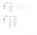
As to the dissipation of energy in resistances, you can check out the second circuit in the attachment. It has a single resistor R3 for charging, and the two caps have resistors in parallel to them that represents the equivalent parallel resistance. By inspection you can see that there will always be energy dissipated in all the resistors.
Red arrows are currents, blue arrows are voltages.
In the first circuit, the upper one, we only have one resistor R3. That resistor causes a delay in charging the two caps and will dissipate energy, but the energy dissipated will come from the battery. The two caps will still charge up to the maximum (1/2 volt each if U=1v) but it will take more time. The charge equation is:
Vc=Vcc*(1-e^(-t/RC))
where RC=R*C.
This leads to a voltage Vc that gets ever so close to Vcc that it can be considered Vcc, but it takes that time 't' to get charged when before it was instant.
You can see two equations in the first circuit. These are the two ODE's that will solve the circuit, and after we solve this we can use some properties to solve any case that uses this configuration even after one or both caps are already charged. I have to ask, do you know how to solve ODE equations? This would be the key to answer ALL of your questions except the ones that involve an actual dissipation that causes a drop in voltage. For that you can use the bottom circuit. If you like you can try to write the ODE's for the bottom circuit, or we can just work with the top circuit for now which will still provide a lot of the answers. Those ODE's will have a form similar to the top circuit equations given.
See what you can make of all this and we can go from there. If this looks difficult don't worry about it because it's not really very hard to solve. There is math software that can do it for us too makes it much easier.
In the end we can come up with a timed switching arrangement to get the voltage up to max if needed.
Attachments
-
 26.7 KB Views: 19
Last edited:
Well it's the most basic way to solve these and leads to simple math that shows how to solve any case we can possibly think of.There's no need to involve differential equations as we don't care about transient behaviors, only initial and final conditions associated with each switching event.
If you want to do it a different way, that's certainly fine, but then you have to explain the math that led you to your solutions, and it may only be good for a single case.
ODE's are so easy to solve with math software it makes sense to look at those solutions.
The solutions are ever so simple too and can be used as is to solve any case where we let the cap voltages vary in any way we want them to. That means we can look at cases we haven't even thought of yet. In the end we also end up with a good theoretical basis for how we got there.
Last edited:
Total and complete overkill.Well it's the most basic way to solve these and leads to simple math that shows how to solve any case we can possibly think of.
If you want to do it a different way, that's certainly fine, but then you have to explain the math that led you to your solutions, and it may only be good for a single case.
ODE's are so easy to solve with math software it makes sense to look at those solutions.
The solutions are ever so simple too and can be used as is to solve any case where we let the cap voltages vary in any way we want them to. That means we can look at cases we haven't even thought of yet. In the end we also end up with a good theoretical basis for how we got there.
Do you solve a nonlinear differential equation to determine how large a current limiting resistor should be in order to get approximately 10 mA of current through a red LED with a 9 V battery?
Certainly you could, and it would let you look at all kinds of cases that we haven't even thought of. But why? It's complete overkill.
So you set and solve a differential equation in order to determine the final voltage across the capacitor in a series RLC circuit connected to a battery? You certainly could, but why?
Hello again,Total and complete overkill.
Do you solve a nonlinear differential equation to determine how large a current limiting resistor should be in order to get approximately 10 mA of current through a red LED with a 9 V battery?
Certainly you could, and it would let you look at all kinds of cases that we haven't even thought of. But why? It's complete overkill.
So you set and solve a differential equation in order to determine the final voltage across the capacitor in a series RLC circuit connected to a battery? You certainly could, but why?
Because we are dealing with energy storage elements that model well in the time domain and the frequency domain, and these are very simple ODE's that quickly reduce to algebra, and this would be a very general procedure that allows us to take it much further without any more difficulty. Heck, it's a resistor and capacitor circuit which we know has various solutions, and I did not want to just hand out something like "just divide by 2" to explain how the voltage transfer occurs. The question then becomes "why do we divide by 2".
This member seems to want to dig deeper and get a really good understanding of how and why these circuits work so I thought I would suggest the most basic starting point so as to reduce questions later, but it was always with the condition that he wanted to do it that way that's why I asked for his opinion on this. If he rejects it, we can default to something else.
Before this analysis is done as least we now have a schematic to work with, at the very least. Also, once this simple analysis is complete, we can analyze different cases such as:
1. Swapping the roles of C1 and C2 (which one in series with the battery to do the voltage charging boost).
2. Changing the values of C1 and C2 to see if different values for one will make anything better, or how it changes the charging speed, if it does at all.
3. Using the same technique, we can add ESR to both caps, parallel resistance, etc., to start to look at real world results.
4. Develop less-general methods for the more common arrangements, including those done using dedicated IC chips made for voltage boosting.
5. Because the analysis starts from such a basic idea in circuit analysis, there should be nothing we can't do, assuming the usual lumped circuit model.
6. If we wanted to skip all that and just jump right to the end, we could state the formula (U-v2+v1)/2 but I don't think this member would learn anything with that.
I would not mind reading how you would like to do it too though. Any method is interesting to me.
Yes, thank you — I’ve understood it now. It really all comes down to the idea that I need to consider how the voltage distributes in the parallel configuration. I’ll take a closer look at the modeling with resistors nowHello again,
Because we are dealing with energy storage elements that model well in the time domain and the frequency domain, and these are very simple ODE's that quickly reduce to algebra, and this would be a very general procedure that allows us to take it much further without any more difficulty. Heck, it's a resistor and capacitor circuit which we know has various solutions, and I did not want to just hand out something like "just divide by 2" to explain how the voltage transfer occurs. The question then becomes "why do we divide by 2".
This member seems to want to dig deeper and get a really good understanding of how and why these circuits work so I thought I would suggest the most basic starting point so as to reduce questions later, but it was always with the condition that he wanted to do it that way that's why I asked for his opinion on this. If he rejects it, we can default to something else.
Before this analysis is done as least we now have a schematic to work with, at the very least. Also, once this simple analysis is complete, we can analyze different cases such as:
1. Swapping the roles of C1 and C2 (which one in series with the battery to do the voltage charging boost).
2. Changing the values of C1 and C2 to see if different values for one will make anything better, or how it changes the charging speed, if it does at all.
3. Using the same technique, we can add ESR to both caps, parallel resistance, etc., to start to look at real world results.
4. Develop less-general methods for the more common arrangements, including those done using dedicated IC chips made for voltage boosting.
5. Because the analysis starts from such a basic idea in circuit analysis, there should be nothing we can't do, assuming the usual lumped circuit model.
6. If we wanted to skip all that and just jump right to the end, we could state the formula (U-v2+v1)/2 but I don't think this member would learn anything with that.
I would not mind reading how you would like to do it too though. Any method is interesting to me.
")
One more thing I wanted to ask: do you happen to know of any method that could go beyond 4U? I’ve been thinking about it for a while — but even when alternating the roles of the two capacitors, the result still seems to converge to 4U. So if it’s actually possible to go beyond that, I guess it would require a completely different kind of approach.


