 Facebook
 Google
 GitHub
 Linkedin
Hai.,
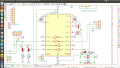
i have made a MAX232 circuit followed by the datasheet and when i give power supply to the board the 232 IC heats up very high .,
https://datasheets.maximintegrated.com/en/ds/MAX220-MAX249.pdf
and i have connected 10uF SMD unpolarized capacitor to my board ...!
but in the data sheet it says to connect only the polarized cap.!
would that be the main reason for the heating issue?
or is there any other issue?
Thanks in advance.,
-saif
Attachments
-
 164.8 KB Views: 25


