Making a 'hot chassis' circuit safe (solv'd)

Thread Starter

metermannd

Joined Oct 25, 2020
343
So, I have this piece of equipment I've reverse engineered and intend to donate to a museum to go with some other items I've donated.

As much as I want to be able to hook up a scope or logic analyzer to the unit to get some more data before I deliver it to the museum curator, I haven't been able to do so as 120VAC is present throughout the unit, even on the DC ground, and even when the unit is switched off!

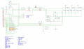
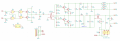
Needless to say, this is clearly a dangerous condition and I want to try and correct it with as little modification as possible. See below for the schematic of the transmitter stage:

I should be able to accomplish my goal by finding the connection between the -170V DC bus (D6 / D8 anode) and the DC ground from J2 and breaking it, right?
 

Attachments

MaxHeadRoom

Joined Jul 18, 2013
28,617
You need to establish if the DC in the unit is galvanically isolated from the AC side, if so you should be able to earth ground all metalic parts of the device in order to make it safe.
 

ci139

Joined Jul 11, 2016
1,898
able to earth ground all metalic parts
the electrician who did our compartment wiring mumbled something about it - the only word i recognized was "unnecessary" - so there is no GND at any of my wall outlets

it might be required to make a sense circuit which will determine the N line and use SSR-s to swap the input according to wall outlet wiring
 

MaxHeadRoom

Joined Jul 18, 2013
28,617
it might be required to make a sense circuit which will determine the N line and use SSR-s to swap the input according to wall outlet wiring
If the OP is in N.A. or one of many other jurisdictions, if the device is not double insulated and has any kind of metallic outer shell, it will require earth grounding.
 

Hymie

Joined Mar 30, 2018
1,277
Where for some reason the chassis of a piece of equipment is live – one method of making it relatively safe is to power the equipment via an isolation transformer.
By doing this, anyone touching the chassis will not receive an electric shock since the supply to the equipment is not referenced to ground/earth.
 

Thread Starter

metermannd

Joined Oct 25, 2020
343
Yes, I'm in North America. Unfortunately the original power cord was lost (the connector is a 28-pin Amp CPC).

I did work out the pinout of the connector, and I just remembered that there is a power distribution board to allow the unit to be powered by vehicle 12V DC.
 

Thread Starter

metermannd

Joined Oct 25, 2020
343
I have this circuit in two different pieces of equipment - an endpoint unit, and the configuration terminal in question.

The configuration terminal is basically a modified endpoint unit, so I grabbed an endpoint unit to trace out the -DC bus on the transmitter board. I can confirm that there is indeed FULL separation between the high-voltage and low-voltage sides of this board. So the ground on the right-hand side shouldn't exist.

That changes everything. I now know where the problem is: there is an add-on power distribution board in the configuration terminal.

It's getting late, so will gather data and post pics / schematic of the power board tomorrow.
 
Last edited:

Thread Starter

metermannd

Joined Oct 25, 2020
343
So, here's the power distribution board in the piece of test equipment (right-hand portion) and chassis wiring. (I still need to get the unit out and get pics of the boards)

The 'D' board referenced is the main low-voltage power supply / interface board (not shown but can upload schematic if felt necessary). Points W11-1, W13, W14 are jumpers from the power distribution board to the two +12V supplies. Points E22, E24, E19 are the input power connections.

The 'B' board is the first schematic I posted, the transmitter board. Points W11-2 and W12 are where this board is connected by jumper to the +170V DC filter capacitor(!!)

The purpose of this board is apparently to give the user the option of swapping the cord that plugs into the external connector for one that allows the unit to be powered up in a vehicle by way of a 12VDC 'cigarette lighter' cord.

I did add a pair of spade lugs in the lead to point W11-2 and even with that lead disconnected, I still had a hot chassis. Am I now correct in assuming that a similar set of spade lugs should be added to the W12 lead?

At this point I just want to be able to safely poke around inside the unit with a scope or logic analyzer.
 

Attachments

Thread Starter

metermannd

Joined Oct 25, 2020
343
Here's a picture of the bottom-side boards.

The larger board consists of Panel B (left) and Panel D (right), then the power distribution board is mounted on top of Panel B.

The large cap on left is C10 (the +170VDC filter), C53 (+12V filter) is the black can to right of the transformer, and C47 (+12VA filter) is the one just right of the main 5V regulator.

The quick disconnect I added runs from C10 (-) to C47 (-). Should I add a similar pair of disconnects in the lead to C10 (+) at bottom? This would be just so I can probe the logic board (on the other side).
 

Attachments

Thread Starter

metermannd

Joined Oct 25, 2020
343
Even adding a disconnect to the other C10 lead wasn't enough to eliminate the AC leakage. There is too much leakage from the 170VDC rectifier bridge to be able to safely poke around the unit when powered from mains, and I don't have an isolation transformer.

HOWEVER, the unit can be powered by an external 12VDC supply, thanks to that daughterboard. I ended up picking up a small 'laptop' style 12VDC power supply and made an adapter cord to access the 12VDC power pins on the unit's connector - it works! I was able to get some of the measurements I'd been after.
 

ag-123

Joined Apr 28, 2017
276
I think (many?) countries requires that non isolated metal enclosures should be connected to the earth wire. This is just in case there is a short to earth. But these days even 3d printers shipped without proper earthing on its smps power supply. another way would be to use an isolation transformer, I'd think most find it bulky/heavy for that transformer and many did without it.
 
Top