I've breadboarded that circuit when other members have tried, and failed, to have an LED turn off completely.
I can't do any calculations for your circuit because you didn't provide supply voltage or LED on voltage. The base current for the transistor that's on has to flow through the LED that's supposed to be off. Any efficient LED will turn on dimly with small currents.
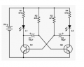
You have a simple multivibrator that alternates two LEDs with two transistors. I would use a CD4017 sequencer IC and an oscillator to make two LEDs each blink twice and alternate. Here is your transistor multivibrator:
That circuit shouldn't work. The LED current will be over 200mA. That means the base current of the transistor needs to be 20mA (unless you're using a Darlington - no part number for the transistor).
With a 9V supply, you'll also be reverse biasing the base-emitter junctions enough to kill transistor beta. Signal diodes anti-parallel to the base-emitter junctions will prevent that.
TIP 120 Darlingtons. The question is not if this works or issues with that circuit. It a way to alter it to give a different effect. I have no issues out of the current circuit.
I've been thinking along the same lines as Audioguru again is. Using a CD4017 and using outputs #0, 2, 5, 7 in a repeating fashion. That way each light is momentarily lit twice with a definite wink-out between, then a short pause, then repeat on the other light. However, this configuration will produce a pulse and not a flash. In order to achieve a flash I would go with a 2 in AND gate. One of the two inputs tied to the output of the 4017 and the other input tied to the clock pulse. The pulse should not be a 50% duty cycle, I'd opt for a 20% duty cycle. That way the LED will more closely resemble a flash as opposed to a pulse. Though output 0 (or any of the other used outputs) may be on for 3/10 of a second, a clock high pulse can be as short as 1/10 of a second and you get your flash. I'll make a crude diagram and post it shortly.
TIP 120 Darlingtons. The question is not if this works or issues with that circuit. It a way to alter it to give a different effect. I have no issues out of the current circuit.
if they are dimly lighting, i cant really tell with a 3watt led. The blue drowns out any white that may be dimly lit and the same vise versa so it does not really matter for either light would be on at a time.
Zipped through the thread and did not see the answer, but I might have missed it ...
Why no IC's? I totally get the no-Arduino, and I support no-555's, but not even simple gates or a CD4017?
The bottom line is of course it can be done with nothing more complex than transistors, because logic chips are made up of nothing more complex than transistors. The problem is the double-blink pattern; something has to count to two to know when to stop blinking and move on to the next part of the pattern. You can do a basic toggle flipflop with two transistors and two diodes - it is a variation of your multivibrator circuit. Two of those and some more transistors for steering logic ... per stage ... the body count will be high.
UPDATE - There is another approach that uses fewer parts. See post #40 and later.
I hope the assortment of ICs from Amazon (China) are not fake ones. Look in Google for the company that makes the assortment: SWPEET. The ad in Amazon is written in Chinglish.
OK, this is NOT a complete diagram. It's intent is to show how I would go about getting the double flash on one side then on the other. The NAND gate chip is a quad dual NAND gate chip. Using two chips for the LED's and the other two chips can be used to create the clock pulse. A bit more complex than you're asking for - but it's how I would have gone about solving the problem. Not shown is the power source and current limiting resistor for the LED's. Also not shown is the two extra NAND's for the clock pulse.
I hope the assortment of ICs from Amazon (China) are not fake ones. Look in Google for the company that makes the assortment: SWPEET. The ad in Amazon is written in Chinglish.
OK, this is NOT a complete diagram. It's intent is to show how I would go about getting the double flash on one side then on the other. The NAND gate chip is a quad dual NAND gate chip. Using two chips for the LED's and the other two chips can be used to create the clock pulse. A bit more complex than you're asking for - but it's how I would have gone about solving the problem. Not shown is the power source and current limiting resistor for the LED's. Also not shown is the two extra NAND's for the clock pulse. View attachment 227374
I'm thinking "ring" oscillator, but that might not be the correct term, I built one many many years ago before I started to use the 40xx line of chips.
I appreciate everyone's input and looks like I'm going to go order some different chip assortments and get this done. However, i had an idea and starting using the circuit simulator and its hard to tell if it will work because the GUI sucks on it at high speeds. What if i made more of the multivibrator circuits and basically feed them off of each other. So, circuit one instead of the LED, connects to 2 of the identical circuits with 2 Identical LEDs in each. so circuit one turn on circuit 2 and blinks LED1 then LED2, then circuit one turns on circuit three and blinks LED3 then LED4 and then back to circuit two. Not that I'm going to make this but curious if it would give me the effect.
Another approach, all transistor, no IC's. A boxcar delay line, a form of a bucket brigade circuit. Cap-resistor-transistor, cap-resistor-transistor, repeat. Diodes combine taps for the double-blink. Your low frequency multivibrator to set the 1-2 second pattern period, plus three pulse stages for blink-pause-blink. 5 transistors. The pattern is triggered by one edge direction of the oscillator, so the other edge can drive a second delay line for the other color LED.
red - short pause - red
longer pause
green - short pause - green
longer pause
repeat
5 transistors for the timing, plus whatever it takes to drive the LEDs. With another possible trick, 7 transistors total.
 Facebook
 Google
 GitHub
 Linkedin