A valuable lesson to learn for a designer is to know what a circuit can do. Anyone designing for 3V output from 1 to 12V input would immediately reject a shunt regulator because it cannot do that.
The IC in a Solar Garden Light boosts the 0.9V to 1.5V from a rechargeable Ni-MH battery cell to 3.5V for a colored LED.
You might be able to copy the circuit in the cheap IC with many transistors.
To boost converter be effective at 1V Vin you need a Bjt with very low Vce_sat. Even 100mV Vce drop causes 10% waist. I usually parallel more bjt-s so every of them carry portion of overall current only.
To design a boost with simple feedback just 2 bjt are needed, one for switching and one as comparator.
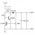
Can you go in detail and explain your circuit how it works, all values of component how they are calculated, what is 1:1 equipment, what is arrow pointing to 100k ohms resistor, why are all the equipment needed and shown? Please also incoming voltage i have baries from 1vdc to 15vdc. You dont have 1vdc to 15vdc you just have 1.5vdc.
This circuit naturally starts oscillate due to positive feedback between coil windings.
When the voltage across coil (right winding) is positive the voltage on auxiliary winding (left winding) is positive also in way it pushes current to base. Once the coil cannot be charged anymore because of bjt Beta the both voltages changes orientation so right winding supplies the cap+load and left winding holds base Off and bjt Off also. This repeates forewer.
And how the 1.5V input is boosted to example 6V? Principally, When you rapidly disconnect a charged coil the voltage across coil changes orientation and huge voltage spike (even 100V is possible) is developed across coil. This huge voltage spike is catch to output cap thru diode.
Note: The mosfet ensures a regulation feedback to maintain Vout constant and for basic functionality (without regulation) is no needed.
The gate of 2n7000 senses output voltage that should be constant 3V if I understand hhsting correctly. Or even more and use linear stabilisation after. So 2n7000 should work I think. But anyway, I would rather make a better comparator than just Vgs of mosfet.
The gate of 2n7000 senses output voltage that should be about 3V if I understand hhsting correctly. So 2n7000 should work I think. But anyway, I would rather make a better comparator than just Vgs of mosfet.
This circuit naturally starts oscillate due to positive feedback between coil windings.
When the voltage across coil (right winding) is positive the voltage on auxiliary winding (left winding) is positive also in way it pushes current to base. Once the coil cannot be charged anymore because of bjt Beta the both voltages changes orientation so right winding supplies the cap+load and left winding holds base Off and bjt Off also. This repeates forewer.
And how the 1.5V input is boosted to example 6V? Principally, When you rapidly disconnect a charged coil the voltage across coil changes orientation and huge voltage spike (even 100V is possible) is developed across coil. This huge voltage spike is catch to output cap thru diode.
Note: The mosfet ensures a regulation feedback to maintain Vout constant and for basic functionality (without regulation) is no needed.
I still dont understand. How did you get capacitor, resistor values? Can you actually show examples of how 3vdc is produced from 1.5vdc? What is the purpose of diode, all resistors, capciators? How is voltage turned on and off??? You show 1:1 is that inductor or transformer? If inductor then what is the size?
I still dont understand. How did you get capacitor, resistor values? Can you actually show examples of how 3vdc is produced from 1.5vdc? What is the purpose of diode, all resistors, capciators? How is voltage turned on and off??? You show 1:1 is that inductor or transformer? If inductor then what is the size?
Read it. Went back to your circuit but its hard to tell which side is positive and which one is negative, which transistors are on or of in cut off or saturation exactly. Is it possible you can go thru and explain it? Please
Forget about mosfet for now. You can even remove it. All switching do a 2n3055 bjt.
If dot of right winding is positive the dot of left winding is positive also.
Look the datasheet of tl431 how a bandgap refference can be performed with transistors. But be ready for very hard study and matching transistors, another words you probably don’t get it.
Building a precise reference is a big topic. Once I reached 1% at 3V output (not a bangap type) and it was true challenge.
Most easy is supply a zener with constant current. You should reach about 2% accuracy at varying Vin voltage (5-12V), but not a temperature compensation:
 Facebook
 Google
 GitHub
 Linkedin