LTspice: Simulating a Van der Pol Oscillator

Thread Starter

Shengyuan Lu

Joined Jul 9, 2019
5
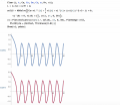
I am trying to simulate the oscillator with an RLC circuit with the initial condition V(V1) = 0 and D(V(V1)) = 0. Since LTspice does not allow initial condition with time derivatives, I set the initial current of the inductor to be -6A. (Initial resistance is 1/3 ohm, and initial current through the capacitor is zero.) It does show a limit cycle behavior, but the amplitude(around 1.2V) is different from the numerical result in Mathematica(2V). I have set all serial and parallel resistance/inductance to be zero for the components. Any suggestions on what could be wrong? Thanks in advance for any advice!Screen Shot 2019-07-10 at 10.52.12 AM.pngScreen Shot 2019-07-10 at 10.51.33 AM.png
 

Attachments

Thread Starter

Shengyuan Lu

Joined Jul 9, 2019
5
Where are you measuring 1.2V? When I run the sim the initial (after 2nS) value of V(V1) is 2V, which agrees with Mathematica.
Hi Alec_t!! Thank you so much for trying that! I measured the node voltage at V1, the net I have labelled on the top of the circuit. The initial value is correct, but the amplitude of the oscillation(limit cycle after running for 15s) is 1.2V instead of 2V.
 
Last edited:

Alec_t

Joined Sep 17, 2013
14,280
Regardless of the original starting conditions (I tried various V1 and I(C1) values), after the initial transient the oscillation settles down to a 1.2V amplitude one.
 

Thread Starter

Shengyuan Lu

Joined Jul 9, 2019
5
Regardless of the original starting conditions (I tried various V1 and I(C1) values), after the initial transient the oscillation settles down to a 1.2V amplitude one.
Yes this fits the characteristic of a Van der Pol oscillator (amplitude of a limit cycle remains constant). Just that the amplitude is different from Mathematica result...
 

Thread Starter

Shengyuan Lu

Joined Jul 9, 2019
5
Replace '-1' with '-3' and you get the 2V amplitude :).
Also, as Alec_t has suggested, if I change the resistance in my Mathematica file to be 1/(3*V(V1)*V(V1)-1) instead of 1/(1*V(V1)*V(V1)-1), the voltage response is exactly the same as the result in LTspice. (The first plot in the picture below is when I change the expression of the resistance, and the second plot shows the overlap with LTspice result.)
On the other hand, all voltage response scales proportionally as expected. For instance, when the resistance in Mathematica is 1/(V(V1)*V(V1)-4), the amplitude doubles and becomes 4V. The amplitude in LTspice also doubles to be around 2.4V when resistance is 1/(V(V1)*V(V1)-4).

I don’t think LTspice has interpreted my original expression of resistance wrongly as I have checked it in a simpler circuit. Hence, I am pretty confused over what else could cause this error, and give a fit when I change the coefficient.

Screen Shot 2019-07-11 at 10.48.10 AM.png
 

Attachments

Thread Starter

Shengyuan Lu

Joined Jul 9, 2019
5
I think LTspice uses the definition R = dV/dI to calculate the response instead of R = V/I.
When R = 1/(V^2-1), I = V/R = V^3-V. Hence if R = dV/dI is actually being used, R = (dV/dt)/(dI/dt) = 1/(3V^2-1) instead, which fits the plot in Mathematica.
I have tried a few other resistors, such as R = 1/(V^4-V^2), and it seems like LTspice uses R = 1/(5V^4-3V^2) too.
If that is the case, is there anyway to adjust the system to reset the definition of R?
 

jshuisman

Joined Mar 18, 2011
1
I think LTspice uses the definition R = dV/dI to calculate the response instead of R = V/I.
?
On Wednesday 10th of july 2019 at 11:28 AM, you posted another circuit with the B source, giving the same output.
That means the difference is not likely caused by the the definition of R.

The implementation of R is incorrect.
This should be R= -=−1/μ(1−1/3*v1^2 )
See https://electronics.stackexchange.com/questions/447616/ltspice-simulating-a-van-der-pol-oscillator for the proof.
 
Top