Facebook
 Google
 GitHub
 Linkedin
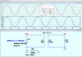
Hi all, I have a problem with an LTspice schematic. When you show a 240vac sine wave source it is not displayed properly unless you show a ground symbol where neutral would be in real life. Then you see, on running, a sine wave with a peak of 336v and negative peak of 336.
How do you then distinguish this ground from your circuit ground?
How do you then distinguish this ground from your circuit ground?