New to LTSpice, what component in this schematic is causing simulation convergence error

Thread Starter

coolyyz321

Joined Mar 17, 2017
90
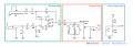
Hello, I am making a simple OP amp circuit based off of MXR's Distortion Plus guitar pedal in LTSpice and I am running into this issue when running a transient simulation. When I run this simulation the program freezes and when I stop the simulation, these convergence errors pop up. Error.png

This is the schematic that I am simulating below
Schematic.png


What could be the issue here? Any help is greatly appreciated.
 

ronsimpson

Joined Oct 7, 2019
4,645
Please post your file.
I don't know why but I would start by removing (.include "lm741.lib") and replacing it with an op-amp from the list.
You might also try replacing the 1N34a.
 
Last edited:

crutschow

Joined Mar 14, 2008
38,314
Hard to tell.

1Meg input and feedback resistors are too large for the typical input bias current of a 741.

Why are you putting two resistors in series?
For simulation purposes one resistor, equal to the sum of the two, will work the same

You can remove R5 since it is shorted.

C1 serves no purpose since V2 is an AC short.

Post your .asc file for the circuit.
 

Thread Starter

coolyyz321

Joined Mar 17, 2017
90
Please post your file.
I don't know why but I would start by removing (.include "lm741.lib") and replacing it with an op-amp from the list.
You might also try replacing the 1N34a.
The lm741 OP amp is a library that I downloaded from TI since it is not included in LTspice. Even with other OP amps that I have tried, there is a similar convergence error. Same with the germanium diode, I make a .LIB file for the diode to emulate it's characteristics.
 

Attachments

Thread Starter

coolyyz321

Joined Mar 17, 2017
90
Hard to tell.

1Meg input and feedback resistors are too large for the typical input bias current of a 741.

Why are you putting two resistors in series?
For simulation purposes one resistor, equal to the sum of the two, will work the same

You can remove R5 since it is shorted.

C1 serves no purpose since V2 is an AC short.

Post your .asc file for the circuit.
I know it seems very unorthodox, but that is what is in the guitar pedal circuit. It's supposed to create a good bit of distortion. The two series resistors are emulating a potentiometer, so I can change the two values to visualize the different waveforms from these. I attached the circuit diagram below.
 

Attachments

Papabravo

Joined Feb 24, 2006
22,058
Unfortunately, spice models and libraries do not come with any sort of provenance or certificate of authenticity. The usual convergence problems arise from steep edges, requiring "small" timesteps and derivatives that are not "smooth". You have to build your confidence level with your tools and pieces parts one step at a time especially when merging "old models" with "new" simulation algorithms.
 
Top