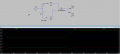
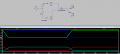
I have a very simple LVDS setup. My impedances are also not matched yet.
I just wanted to see and compare my inputs vs outputs. What is strange is that there is no DC component at the output. The reference is set to 0.
Not sure I understood your point. At my input,
V_common = 1/2 (v_1+V_2)= 1/2 (1.75+0.25)=1 V.
Thus, i was expecting that output will have the same common voltage though output voltage values might differ due to impedance mismatch. But my DC component is 0
I see no definition of V2 or V3. Perhaps the simulator sees them as open circuits??
AND, I am not familiar with whatever the symbol "T1" is representing, although the text implies it might be a transmission line of some sort.
I think I have figured it out the issue.
My idea was that if my LVDS has Vcommon of 1 V which is also my Dc bias, I would get it on the output too.
But in LTSPICE, the TL model is only for one mode communication and I would need at least one more TL . there is an example in "help" but its is hard to follow for me, and I was wondering how to get the VCommon also on output.
hi am1,
This sim shows that the Common voltage V=0v or if V=1v, it is added to the positive and negative amplitude of the pulses, so at the Vout they always cancel out, no DC offset.
E
hi am1.
Look at this test sim, the tline component is removing the DC component on the input signal.
I have used simple +1V DC signal on one of the inputs, which is removed by the tline.
E