LTSpice Programmable Load

Thread Starter

josephoh135

Joined Oct 14, 2024
10
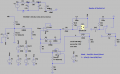
Hello, I have an LTSpice simulation of a programmable load for a battery cycler project I am working on. Some issues I am facing is that whenever Vds drops Vgs increases, changing the MOSFET operating region from saturation to linear. It may be component parameters or an incorrect circuit configuration, but any advice helps. I want to operate the FET in linear region and measure a near constant current at the drain. Any advice helps. At the top is also a arduino pwm control I want to apply for the gate voltage. I am assuming that Vgs should not change in response to a change in Vds.1731834431943.png
 

liaifat85

Joined Sep 12, 2023
200
If you're using an Arduino to control the gate voltage with PWM, ensure that the gate voltage (Vgs) is sufficiently above the MOSFET's threshold voltage (Vth) but not so high that it causes significant Vds dependencies or excessive power dissipation. Typically, Vgs should be kept at a level where the MOSFET operates in the linear region but avoids saturation.
 

Thread Starter

josephoh135

Joined Oct 14, 2024
10
UPDATE: Realized the MOSFET has too low of a threshold voltage and may be affecting my output. Currently, trying to find one with a high Vth and Rds(on) if yall have any recommendations. Might also need a different opamp, too.
 

ericgibbs

Joined Jan 29, 2010
21,390
hi j135,
This is an edited version using your IRLZ model, please check for accuracy.
The zip file contains the asc, sub and asy files, for anyone else who helps.

E
EG57_ 2311.png
 

Attachments

crutschow

Joined Mar 14, 2008
38,316
What are all the unrelated circuits in your schematic, which are rather confusing?
Please post just the part of the circuit your are simulating for the battery current load.

Why are Rset1 and Rset2 set to 100,000 volts?
 
Last edited:

Thread Starter

josephoh135

Joined Oct 14, 2024
10
The empty isolated voltage sources act as control and apply their value to a resistor or voltage supply. Rset1 and Rset2, though labeled as 100k is applied on the Rvar1 and Rvar2 as R=V(Rset1) to basically just say the resistor's resistance is 100k. The extended circuit to the right is in place if there is a necessity to add more MOSFETs and to the left acts as the PWM source I plan to put in, currently I was having trouble getting figuring out why my Vgs was reacting to the change in Vds and I thought that it may have been an insufficient supply voltage at the noninverting end of the opamp and for now put a Vsup to control it as 5V for now. When connected, Vsup is removed and connected to R3 and C1 where now Vfb, the PWM signal from the arduino, will act as a the Vsup. The Vds voltage source is acting as my "Battery" which don't actually have a constant voltage but will charge and discharge from 2-4.1V which I say is my "change" in Vds by replacing the Vds value from 2-4.1V.
 

crutschow

Joined Mar 14, 2008
38,316
A 4.5V Vsup signal will generate a theoretical current of more than 4.5kA through Rs1 [(4.5V*U2-gain) / Rs1].
I think you need to go back to the drawing board.

What, exactly, is the circuit supposed to do?
What is the purpose of the variable resistances?
 

Thread Starter

josephoh135

Joined Oct 14, 2024
10
Circuit is supposed to be constant current programmable load and discharge a constant current up to 5 amps. Vsup is just a random value I've been messing with to see how the signals react. Tbh, not too sure the purpose of variable resistances, besides a voltage divider for the pwm signal, and yes definitely need to work on understanding the different parts of the circuit. I referenced this circuit on reddit. The formula definitely helps, thanks.
 

Thread Starter

josephoh135

Joined Oct 14, 2024
10
Programmable how?
Programmable, in that the PWM will be controlled through a microcontroller and applied to the Mosfet gate and maintain that applied Mosfet gate voltage despite the natural discharge of battery at the drain. Currently, the voltage at Vgs remains constant in response to a change in Vds, however the current is not constant and drops as battery voltage drops.
 
Last edited:

crutschow

Joined Mar 14, 2008
38,316
Programmable, in that the PWM will be controlled through a microcontroller and applied to the Mosfet gate and maintain that applied Mosfet gate voltage despite the natural discharge of battery at the drain. Currently, the voltage at Vgs remains constant in response to a change in Vds, however the current is not constant and drops as battery voltage drops.
What's the battery voltage?
 
Top