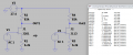
LTspice of J201, J113

Thread Starter

rpschultz

Joined Nov 23, 2022
808
I have a guitar circuit that uses a J201, these are expensive and hard to find in thru-hole. I wondered if I can substitute a J113 instead. Here's the original circuit:
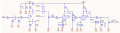
1774049983748.png

Here's my spice model:
1774050408554.png

I suspect I need to change the 6.2k, but I'm not sure what I'm looking for.
 

Thread Starter

rpschultz

Joined Nov 23, 2022
808
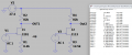
Changing R3 to 12.5k seems to get the current through R1 and R3 to be the same as well as the output voltages. I have looked at the datasheets but am not sure what parameter is causing this difference. I doubled R3, suggesting there's a gain parameter that is twice/half as much.

1774051051221.png
 

schmitt trigger

Joined Jul 12, 2010
2,081
It is called Idss.
For the J201 it has a min/max range of 0.2 to 0.9 mA.
For the J113 it is listed as 2 mA min, no max range specified.

The problem with JFETs is its very wide Idss span. In that instance, the J201 is superior as it is binned for a range, whereas the J113 only specifies minimum value, and its maximum can be anywhere else.
You would probably require a pot to adjust the actual bias.
 

Danm1

Joined Jul 19, 2010
75
A possible solution is solder the surface mount j201 to a tiny board that has pins or holes, then solder this tiny daughter board to your board. You can have a company like Proto Advantage do up the daughter board with your specified part.
 

Ian0

Joined Aug 7, 2020
13,126
It is called Idss.
For the J201 it has a min/max range of 0.2 to 0.9 mA.
For the J113 it is listed as 2 mA min, no max range specified.

The problem with JFETs is its very wide Idss span. In that instance, the J201 is superior as it is binned for a range, whereas the J113 only specifies minimum value, and its maximum can be anywhere else.
You would probably require a pot to adjust the actual bias.
The datasheet is common for J111, J112 and J113. That suggests that if Idss of a J113 exceeded 5mA, then it would be a J112. So in effect, they are binned: The last digit is the bin!
The Id/Vd graph only covers a very small area, if you were to extrapolate to 35V then you could design it with a printout of the curve and a ruler, as if you were designing for triode valves. Using a source resistor to bias it will reduce some of the spread.
I was wondering if you could get SPICE to draw the curves, but the model that came with my LTSPICE is very simplistic, and just approximates its characteristics to two straight lines.
By the way, I've use J113 in guitar circuits before and it works nicely.
 

Ian0

Joined Aug 7, 2020
13,126
Have you measured Idss for your J113s? Short gate and source, and connect it across a 15V power supply and measure the current through it with a meter.
 
Top