LT1366 circuit not producing the correct output.

MisterBill2

Joined Jan 23, 2018
28,206
It's 8k ohms across pin 1 and pin 2

Yeah I understand. There's a lot of wasted space on the board but I don't intent to make anymore of them. They were just for me so I'm not too fussed.
It's mainly because it was auto-routed however I wouldn't have even thought to change it so I'll keep it in mind for my next circuit board.
OK that it was done by an auto-router. I suggest examining the design rules settins for that program, and making some adjustments. Certainly an auto-router can be a great help,but they can also do some really strange things. AND there is a big difference between the $500 versions and the $72,000 versions.
 

Thread Starter

Bod

Joined Sep 18, 2016
317
Update. It's my fault. I have never had and never used an oscilloscope before. Even though the one I bought was simple, I still had a bit to learn. It turns out I was using the wrong coupling. I was using GND which centres everything on 0 volts. I needed to use DC coupling which shows all of the input signal.
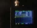
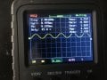
Here's the new info. On my circuit board, the output of the first chip is:
IMG_1112_.JPG
That looks good. It looks to me like it is biased at 2.5V. The breadboard output also looks this (again this is just from the first chip).
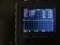
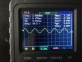
If I probe the output of the second chip on the breadboard, it looks exactly the same, of course it's just inverted. The output of the second chip on the circuit board looks like:
IMG_1117_.JPG
So I can say for certain it's to do with the second chip circuit. I haven't re-flowed them yet and I am going to do it now.
I apologise for the confusion.
 

MisterBill2

Joined Jan 23, 2018
28,206
What I see is aa very much clipped signal. So I suggest reducing the input peak-to-peak voltage quite a bit, and at some point the distortion will be gone and the output will look like the input, but with a different amplitude.
And certainly using an oscilloscope does require a fair bit of understanding how to adjust it for what you want to see.
 

Thread Starter

Bod

Joined Sep 18, 2016
317
What I see is aa very much clipped signal. So I suggest reducing the input peak-to-peak voltage quite a bit, and at some point the distortion will be gone and the output will look like the input, but with a different amplitude.
And certainly using an oscilloscope does require a fair bit of understanding how to adjust it for what you want to see.
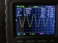
I don't know if it's because I'm using my oscilloscope wrong but measuring the output of my signal gen gives this:
IMG_1118_.JPG
That's set to 5V per division. That would suggest my output signal is a huge voltage (9V). That would make sense as to why it's clipping since my circuit does 0-5V max.
However, in general this doesn't make sense because why would I get a -9 to 9V sine wave especially on a 5V powered signal generator?
 

MisterBill2

Joined Jan 23, 2018
28,206
I don't know if it's because I'm using my oscilloscope wrong but measuring the output of my signal gen gives this:
View attachment 210247
That's set to 5V per division. That would suggest my output signal is a huge voltage (9V). That would make sense as to why it's clipping since my circuit does 0-5V max.
However, in general this doesn't make sense because why would I get a -9 to 9V sine wave especially on a 5V powered signal generator?
It is certainly possible, at least in theory, to get a 10 volt peak-to-peak signal from a 5 volt sourced circuit, if the output section is a "bridge" type. And this large signal certainly explains the clipping. But this signal is above 20 volts PP, and so there is an error someplace in the measurement arrangement. A fist guess is that the scope is thinking that the input is from a 10:1 probe while really it is a 1:1 probe. If that is the case then the actual signal is about 2 volts PP, a believable number.
So the first suggestion, again, is to reduce the amplitude of the input signal until the output looks undistorted. Then check the input amplitude.
 

Thread Starter

Bod

Joined Sep 18, 2016
317
It is certainly possible, at least in theory, to get a 10 volt peak-to-peak signal from a 5 volt sourced circuit, if the output section is a "bridge" type. And this large signal certainly explains the clipping. But this signal is above 20 volts PP, and so there is an error someplace in the measurement arrangement. A fist guess is that the scope is thinking that the input is from a 10:1 probe while really it is a 1:1 probe. If that is the case then the actual signal is about 2 volts PP, a believable number.
So the first suggestion, again, is to reduce the amplitude of the input signal until the output looks undistorted. Then check the input amplitude.
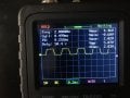
I'll give that a go. I have reflowed the components and it has affected the output. Here's the output of the second chip after reflowing:
IMG_1119_.JPG
It's a lot cleaner than before but it still does look like it's clipping a lot so I'm going to give what you said a go. But I mean it's an improvement either way because I wasn't getting anything out of the second chip before reflowing.

EDIT: Didn't take long. Adjusted the amplitude until it was no longer clipping. Here;s the output of the second chip:
output.JPGAnd here's the input from the signal gen:
input.JPG
 
Last edited:

Audioguru again

Joined Oct 21, 2019
6,826
I am glad to see that you got it to work but the LT1366 opamp is a poor choice for audio:
1) It is almost the noisiest opamp ever made.
2) It has a poor high frequency response and an extremely poor slew rate. Its slew rate is so low that it is specified only when the supply is plus and minus 15V and it is probably less at your 5V supply.
 

Thread Starter

Bod

Joined Sep 18, 2016
317
I am glad to see that you got it to work but the LT1366 opamp is a poor choice for audio:
1) It is almost the noisiest opamp ever made.
2) It has a poor high frequency response and an extremely poor slew rate. Its slew rate is so low that it is specified only when the supply is plus and minus 15V and it is probably less at your 5V supply.
I see. Maybe one day I can improve my circuit. For now, it's going to be fine for me.

Thank you!
 

MisterBill2

Joined Jan 23, 2018
28,206
Since the connections to that LT1366 IC are quite standard, an upgrade will be as simple as unplugging that device and plugging in another one with better specifications. Sometimes changes can be easy!
 

Thread Starter

Bod

Joined Sep 18, 2016
317
Since the connections to that LT1366 IC are quite standard, an upgrade will be as simple as unplugging that device and plugging in another one with better specifications. Sometimes changes can be easy!
I didn't think of that but you're right. They are literally just generic op-amp connections. I would just have to make sure I was 100% certain that the new chips I would be buying would work. And to be honest, for my circuit, it's not too big of a deal. Noise really doesn't make much difference because I'm not looking for accuracy. The main improvement would be price since LT1366's are quite pricey.
 

Audioguru again

Joined Oct 21, 2019
6,826
For audio, the noise from the opamp will be hiss all the time.
The poor frequency response will make sounds muffled with distorted high frequencies.
The poor slew rate will cause higher frequencies to intermodulate each other producing lower frequencies that is an odd-sounding distortion.
The high cost is because the opamp is rail-to-rail.
 

Thread Starter

Bod

Joined Sep 18, 2016
317
For audio, the noise from the opamp will be hiss all the time.
The poor frequency response will make sounds muffled with distorted high frequencies.
The poor slew rate will cause higher frequencies to intermodulate each other producing lower frequencies that is an odd-sounding distortion.
The high cost is because the opamp is rail-to-rail.
It's all coming back to me now. You mention rail-to-rail and that's the exact reason I bought because I didn't want to supply them with +-5V. Luckily I'm not playing any of the output otherwise I would be quite disappointed!
 

Audioguru again

Joined Oct 21, 2019
6,826
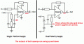
If you bias it at half the supply voltage and use input, output and feedback to ground coupling capacitors, an opamp does not need a negative supply. Then use a +5V to +30V supply.
Rail-to-rail means the output swing is a little higher than an ordinary opamp. An ordinary opamp will have an output that is a little higher when its supply voltage is a little higher.
 

Attachments

MisterBill2

Joined Jan 23, 2018
28,206
If you bias it at half the supply voltage and use input, output and feedback to ground coupling capacitors, an opamp does not need a negative supply. Then use a +5V to +30V supply.
Rail-to-rail means the output swing is a little higher than an ordinary opamp. An ordinary opamp will have an output that is a little higher when its supply voltage is a little higher.
I think that there is something special about the TS application that makes the easy way not possible. BUT at least we have it working now.
 

Thread Starter

Bod

Joined Sep 18, 2016
317
If you bias it at half the supply voltage and use input, output and feedback to ground coupling capacitors, an opamp does not need a negative supply. Then use a +5V to +30V supply.
Rail-to-rail means the output swing is a little higher than an ordinary opamp. An ordinary opamp will have an output that is a little higher when its supply voltage is a little higher.
So for the circuit you provided, would you need a rail-to-rail op-amp or could you go without one?

In hindsight it would have been more cost effective to plan my circuit using a breadboard which would have allowed me to change my circuit to easily and test different ones like you have shown.
Hopefully at some point in the near future I will re-make my schematic (since there's a few other issues as well) and swap out the circuit for a better choice.
I think that there is something special about the TS application that makes the easy way not possible. BUT at least we have it working now.
Exactly! At least it's working now and I can put it away and not have to worry.

Thanks for all the help!
 

Audioguru again

Joined Oct 21, 2019
6,826
You only need a rail-to-rail opamp when you need all the output voltage swing that the supply voltage allows.
With a 5V supply the maximum unloaded output of a rail-to-rail opamp is 5V peak-to-peak. But an ordinary opamp maximum unloaded output is 3V or 2V peak-to-peak.

Use an IC socket if you want to change "through hole" opamps.
 

Thread Starter

Bod

Joined Sep 18, 2016
317
You only need a rail-to-rail opamp when you need all the output voltage swing that the supply voltage allows.
With a 5V supply the maximum unloaded output of a rail-to-rail opamp is 5V peak-to-peak. But an ordinary opamp maximum unloaded output is 3V or 2V peak-to-peak.

Use an IC socket if you want to change "through hole" opamps.
That makes sense. That would mean I would have needed like a 7 or 8V supply which is quite a random voltage. To be fair, with the way I ended going to power the board it actually wouldn't have been hard to get that voltage but at the time it was quite difficult.
 

Audioguru again

Joined Oct 21, 2019
6,826
That would mean I would have needed like a 7 or 8V supply which is quite a random voltage.
A 9V battery voltage drops to 6V or a little less over its life which will be fine for a rail-to-rail opamp but then some ordinary opamps might not work. Read the datasheet of the opamp so see its minimum recommended supply voltage for whatever output voltage swing you need.
 
Top