Facebook
 Google
 GitHub
 Linkedin

Hello to good people that know me.
- Do you know how a capacitor discharge circuit looks like in a modern multimeter?
I already tried a couple of circuits I could think of, but ... problems:
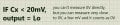
1-it needs to discharge an unknown charged capacitor to 0V on the + lead, lets say 1000 or 5000uF, which means a lot of charge or current stored.
2-then -compare- when is fully discharged at 0V (or close to it) and send a Hi to microcontroller pin, that in turn can start measuring, meaning charging the cap to a programmed value. Switch between discharging circuit to mcu testing pins when Cx is empty and safe.
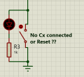
3-resolve when Cx is not connected or when pads are floating.
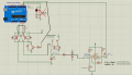
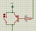
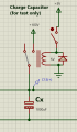
What I've tried:
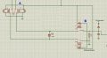
#1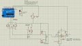
#2
Thank you !
- Do you know how a capacitor discharge circuit looks like in a modern multimeter?
I already tried a couple of circuits I could think of, but ... problems:
1-it needs to discharge an unknown charged capacitor to 0V on the + lead, lets say 1000 or 5000uF, which means a lot of charge or current stored.
2-then -compare- when is fully discharged at 0V (or close to it) and send a Hi to microcontroller pin, that in turn can start measuring, meaning charging the cap to a programmed value. Switch between discharging circuit to mcu testing pins when Cx is empty and safe.
3-resolve when Cx is not connected or when pads are floating.
What I've tried:
#1
#2
Thank you !
Last edited: