Capacitor discharge circuit in modern multimeter

panic mode

Joined Oct 10, 2011
5,240
using constant current makes response linear and this is just nicer and easier to handle.
you can use

C=I*(t2-t1)/(V2-V1)

and keep track of units (F,A,s,V) or replace them with uF,mA,ms,V.

example

t1=0ms, V1 = 0.75V
t2=250ms, V2 = 3.2V
I=10mA

C=10mA* 250mS/2.45V=1020uF
 

WBahn

Joined Mar 31, 2012
33,175
Clearly the this thread is about LARGE capacitors, with high values of capacitance.
Is it? The largest I've seen is 5000 µF (and leakage current is likely a factor there), but he's also talking about 1 pF.

If he is talking about large capacitors at hundreds of volts and being concerned about protecting his equipment if he forgets to discharge the cap before connecting it, perhaps he shouldn't be messing around with large capacitors charged to hundreds of voltage to begin with.
 

WBahn

Joined Mar 31, 2012
33,175
using constant current makes response linear and this is just nicer and easier to handle.
you can use

C=I*(t2-t1)/(V2-V1)

and keep track of units (F,A,s,V) or replace them with uF,mA,ms,V.

example

t1=0ms, V1 = 0.75V
t2=250ms, V2 = 3.2V
I=10mA

C=10mA* 250mS/2.45V=1020uF
The same is true using a constant voltage and first-order response.
 

Thread Starter

q12x

Joined Sep 25, 2015
2,244
I think I got it.
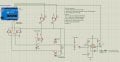
I also made some modifications to the big circuit. Turns out charging capacitor is necessary after all. I was only using it to simulate some extremes, but is important to include it into the final logic. I also made a new transistor command module for it, the (B) module.
I also included 100k in the input comparator as you suggested. That is good observation. The clamp diodes remain there because Im not modifying the comparator configuration as you shown earlier.
The charge Cx voltage is now 5V (or +1V) for the logic of operation. Again, earlier I was testing with 100V as an extreme. It is still not safe for the comparator input if the voltage is too high. Is not perfect yet, and this part might need some further tweaking.
Read Order of operation. That I was concentrated all this time, right before opening this thread. This is I was after.
Writing down all these problems, helps. Plus your critique, of course. Any pseudocode corrections are welcome.
Screenshot_1.jpg
This might be the final version of the circuit. Excluding some switches used only for simulation. I might update the circuit with NPN or N-Ch mos, rewiring everything, instead of those PNPs. Will see.
- I made a mistake not mentioning the full scale of Cx I intended. I was thinking too far ahead. I want from 1pF to 1000uF(or 5000uF) range. The small Cx range, 1pF-100nF I guess, can be safely discharged on the mcu pins, if they are not too high voltage. Ive seen a lot of tutorials out there doing exactly this. So its not my idea. But they never mention the voltage of these small caps like I do here. The bigger caps are a problem and I concentrated only on them here in this thread, as it seems.
 

MisterBill2

Joined Jan 23, 2018
28,227
I have used my EICO model "950 B" bridge to measure capacitors. Usually I just read the markings and those values are adequate for my applications. ACCURATELY MEASURING capacitance is always a challenge.
One thing sbout the methods described so far is that they all require accurate measurement of some other variable quantity.

I usually design circuits with adjustability available rather than spend on close tolerance parts.
How close does a 1000MFD filter cap need to be?? Even if it is used for DC isolation in the output of an audio power amp, leakage and power handling are the more important values.
For very small values used in RF tuned circuits, the LC pair is tuned to resonance rather than using specified exact values.

I wish the TS GOOD LUCK on finding an adequate scheme for good accuracy in measuring capacitance!!
 

panic mode

Joined Oct 10, 2011
5,240
i do not know what relays you use but relays with low voltage coils need more current to drive. driving several of them (you have 4 on "circuit A") means you need even more current. so BJT will need some healthy base current which 10k resistors R2 and R4 cannot supply. more appropriate value here would be fraction of a kOhm... but not too low or you would be stressing those GPIO.
if you are using5V to charge the caps, there is no need for diodes and R5 (comparator inputs can handle that easily) but they certainly do not hurt. it would be a good idea to use the same thing on the ADC inputs. btw, one of your ADC inputs (A0) is either floating or tied to GND. what is this good for?
 

Thread Starter

q12x

Joined Sep 25, 2015
2,244
How low do you think I can go with the cap values in this circuit?
Could it be 1-2pF ?or 10pF,or 100pF? Im afraid of the very long wires/tracks also through the relay contactors.
From what I know, I think it can be compensated in software....but I bet it is tricky.
- You guys mentioned I should concentrate on making small cap reading using an oscilator and then reading the frequency because that is giving the best and most precise result. Right? If this turns out to go low as 1nF but useless in pF, is what I suspect and Im afraid, then... I will make a secondary circuit toggle from a switch that can do the smaller values, I guess ? I wished all in the same basket, but will see how low it will get.

one of your ADC inputs (A0) is either floating or tied to GND. what is this good for?
A0 and A2 are the testing pins of the mcu. Nothing is tied to ground. Oh, I think you follow the line to the 300R which is tied to ground indeed. Remember, those mcu pins are disconnected and connected to the CAP itself. Not to what comes after the cap. Read again #13, because I clarified it there already.

a good idea to use the same thing on the ADC inputs.
yes, you are right. The 2 ESD clamp diodes pair to A0 and A1. Im not sure about putting resistors on A0 and A1 lines, because it will slow the cap reading. I think. I will test them when the thing is build and working.

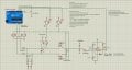
Here is the updated cct, I dded esd clamp diodes for mcu pins + 10k resistors. The simulator is making funny faces if Im using too high like 100k on the cmpr input. So I lowered to 10k to be simulatable. I read the "High res cap meter with PIC 16F628" webpage from earlier suggestion and I also inserted into my project that Zero Calibration button ... IF it will be able to read any pF !
I made a new note there, saying: for 1pF measurements, the charge pulse and the check must be faster than the discharge time of the 1pF capacitor.
And I find the answer also. τ=300Ω×1 pF=300 ps This means the pulse must be less than 300ps. Arduino can operate in us. So...the lower limit is around 100nF, I guess. Phuuuui ai ai ai.
Screenshot_3.jpg
 
Last edited:

Thread Starter

q12x

Joined Sep 25, 2015
2,244
Do you really need all those components and complex solutions when you already have an AVR equipped with timers, an ADC, and a comparator?
https://electronics.stackexchange.c...derstand-an-arduino-capacitance-meter-program
Hi Jony,
- This is all I could think of. Like I said, this is my first shot at this kind of circuit, my first time.
All I realized in the past week, was that the measurement is done directly on the mcu pins, from the bunch of internet examples. That was my realization. I really liked the idea of measuring Cx on the input of a comparator or some pins from a 555 timer, literally protecting the mcu pins from contact with the Cx when unknown charged. So then my next thought was to create a very strong protection for the mcu pins. Im afraid of measuring Cx directly on the pins of the mcu, thats why all the protection. Thats why I started the thread about protection, because I have no clue how to do it. Its my first time also. And how much protection it needs? What is good enough?
- I usually have the most used capacitors, a large majority scrapped, of various small and high values.
A lot of 16V, 25V, 50V @ 1uF, 10uF, 100uF also 1nF,10nF,100nF's. I also have 1nF 2kV,4kV ones.
Most probably all discharged and also already tested on my other capacitor meters I have.
I do not have those big and fat type of capacitors, used in welding machines or industrial equipment. I keep my distance from those.
What I have are the 'usual' every day electronics capacitors. Also some power supplies ones but I almost never find a use for those.
- My goal is to have a very good and reliable cap meter. One with very low pF range, but also with high 1000uF range as well.
My best DMM that can measure capacitance, is old and is not measuring correctly anymore. It has its moments but is starting to
loose its credibility. Something inside him is deteriorating is my guess. And is intermitent, sometimes is good, others is out there.
Thats my motivation, to have an equivalent or better cap meter than my old trusty DMM.
 

Thread Starter

q12x

Joined Sep 25, 2015
2,244
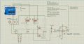
Updated circuit:
Check it for errors or mistakes please.
I changed previous PNP's on top with those 2xN-Ch Mosfets. The (A) N-Ch mosfet is driving correctly this time the relays.
I also change the logic. Now when cap is charged, output=Hi, when discharged or unconnected, output=Lo.
Im also troubled for the difference in potential between lets say a charged cap at 100V (as an extreme case) and that diode on (B). Will not that cap higher voltage surge its current towards that 5V supply? Because is seeing it at lower potential, pretty much like a ground it will be for it. Its the only problem I can see so far.
Screenshot_1.jpg
 
Last edited:
Top