Facebook
 Google
 GitHub
 Linkedin
Hi Guys,
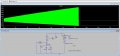
Please find attached simulation file attached.
V1 = 254Vrms
I1 = 4A Inductive load
D1 =D2 = FM4007 ( I am not able to find same part number so tried with equivalent)
D3=D4 = 47V Zener ( I am not able to find same part number so tried with 51V Zener equivalent)
I want switch on and off AC (V1) for 20s ON and 10S off for testing. And this is to be controlled by switch and i am not able to design model for the same.
While performing this test R1 is getting open.(https://www.mouser.in/datasheet/2/447/Yageo LR_FMP_2013-594466.pdf)
So i want to simulation what spikes at R1 during turn on and off.
Could anybody help me on the same issue ?
Regards,
Attachments
-
2.4 KB Views: 4


")