
Hi,
My requirement is that I have an input of 10VC to 32VDC and I have to design a power supply that can convert the said input to 12VDC with a capability of sustaining load of 310mA minimum.
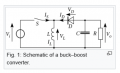
As i am looking for a cost effective solution it will require me to design a discreet buck boost regulator with no ICs used. The switching should done by some kind of feed back circuit.
Can anyone please suggest a design or a similar design that i can use here.
My requirement is that I have an input of 10VC to 32VDC and I have to design a power supply that can convert the said input to 12VDC with a capability of sustaining load of 310mA minimum.
As i am looking for a cost effective solution it will require me to design a discreet buck boost regulator with no ICs used. The switching should done by some kind of feed back circuit.
Can anyone please suggest a design or a similar design that i can use here.
") . It is required for a real-world product. As there are cost constraints that are to be adhered to I am more inclined on a discreet solution rather than choosing an IC.
. It is required for a real-world product. As there are cost constraints that are to be adhered to I am more inclined on a discreet solution rather than choosing an IC.


