Low battery indicator, what am I doing wrong?

Thread Starter

MrSoftware

Joined Oct 29, 2013
2,273
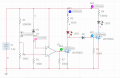
What have I got wrong here? I think my circuit is OK, but the simulator disagrees, but I suspect the simulator is confused or I'm not using it correctly.. In theory, with Vbat at 9V, Q1 will be on and the green LED will be lit. As the voltage drops Q1 will turn off, Q2 will turn on and the red LED will light. I've got a pair of 3.3v zeners in series controlling the voltage to the gate of Q1. However, the simulator tells me that even with Vbat = 20V, the Q1 gate voltage is 0, which can't be right.

Ultimately I want the green LED to go out and the red LED to come in when Vbat hits around 7.2v, but I was at the mercy of the parts available in the simulator so I know I'll be off of those values. Since PartSim isn't useful here, does anyone see an error in my general logic (I know the values will need tweaking)?

upload_2018-9-13_21-34-47.png


upload_2018-9-13_21-37-32.png
 
Last edited:

k7elp60

Joined Nov 4, 2008
562
The schematic shows a 1N4004 as a green LED? I question that as a1N4004 is a diode rectifier. If the LED in the circuit is a small 3mm of 5mm, the forward current is greater than 20mA. I calculate Q1 is turned on as the gate voltage is 9.0V -(3.3 +3.3) or 2.4 volts.
I do not think Q2 will even turn on if Q1 is trurned on. I wonder of the Zener diodes are even conducting as the zener current would be
about 240uA.
 

Thread Starter

MrSoftware

Joined Oct 29, 2013
2,273
Follow up; I tried MultiSim and it works more or less as I expected, so my logic is mostly good, though Q1 isn't turning on/off as sharply as I like resulting in some time with both LEDs on. Is there a better way that doesn't involve additional fets to control the gates on these fets? I'm going for low cost.

upload_2018-9-13_22-15-54.png

upload_2018-9-13_22-16-17.png
 

Thread Starter

MrSoftware

Joined Oct 29, 2013
2,273
The schematic shows a 1N4004 as a green LED? I question that as a1N4004 is a diode rectifier. <...snip...>
No, that simulator didn't have any "LED"s so I just used a regular diode for the basic behavior. The MultiSim simulator seems to be infinitely better, see my above post. I'm open to all suggestions to get Q1 and Q2 to operate in a more binary fashion if possible..
 

Thread Starter

MrSoftware

Joined Oct 29, 2013
2,273
An OpAmp controls the gate on the fet in more of a binary way, with the schematic below my green LED is fully on at 7.4V and the red LED is fully on at 7.3V which is great, but the parts count is too high (too much $$). Can anyone suggest a better way?


upload_2018-9-13_22-53-25.png

upload_2018-9-13_22-54-16.png
 

Attachments

Sensacell

Joined Jun 19, 2012
3,784
The 'soft knee' and poor voltage tolerance of garden variety zeners make them pretty crappy for this application.

I would use an AN431 for example, $0.06 in quantity.
 

crutschow

Joined Mar 14, 2008
38,503
Here's a circuit that uses an inexpensive TL431 programmable zener IC (same as the AN431 I believe) as a comparator to give an accurate and sharp transition between the red and green LEDs.
The transition occurs at about 6.8V with the component values shown.
That switch point is when the voltage at the TL431 Sense input equals 2.5V.
This can be made adjustable by replacing R2 and R3 with a 10kΩ pot (wiper to Sense input).

The TL431 cathode voltage when low (sense input above 2.5V) is about 2V, so two red LEDs are used in series to get sufficient forward voltage to insure that they are off for that condition.

upload_2018-9-13_19-59-37.png
 
Last edited:

Thread Starter

MrSoftware

Joined Oct 29, 2013
2,273
Thank you very much for the suggestion! What simulator are you using? It appears that the free version of MultiSim won't let me add the TL431a.
 
Top