Facebook
 Google
 GitHub
 Linkedin
I will try and do that, to make them more readable from now on.
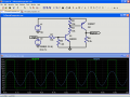
Here is my latest attempt, please grade on readability and functionality
Also, which software did you use to simulate it? I'm still trying to keep up with your math
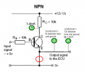
Assuming the Vf of the LED would be about 1.8v, the BE junction would be around 0.7v:
12v-(1.8+0.7)=12-2.5 = 9.5; 9.5v/2.2k Ohms = 4.32mA base current.
Meaning that the voltage forward of the LED is 1.8v (voltage traveling through it?)
Then at the Base, .7v is "consumed" (how did you know it was .7? because that is what it takes to trigger the NPN?)
With those two figures, you calculated 9.5v where?

Here is my latest attempt, please grade on readability and functionality
Also, which software did you use to simulate it? I'm still trying to keep up with your math
Assuming the Vf of the LED would be about 1.8v, the BE junction would be around 0.7v:
12v-(1.8+0.7)=12-2.5 = 9.5; 9.5v/2.2k Ohms = 4.32mA base current.
Meaning that the voltage forward of the LED is 1.8v (voltage traveling through it?)
Then at the Base, .7v is "consumed" (how did you know it was .7? because that is what it takes to trigger the NPN?)
With those two figures, you calculated 9.5v where?
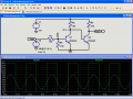
Then, figure the transistor is pretty well saturated, so Vbe will be very low - maybe 100mV or less. Anyway, we'll thrown it in there.
12v-(1.8+.1)=12-1.9 = 10.1; 10.1v/1k Ohms = 10.1mA.
So, 4.32mA + 10.1mA equals...
14.42mA.
On bjt orientation:
Have the arrow in the emitter pointing towards the bottom portion of the schematic.
For a PNP transistor, the emitter arrow points towards the base; so in order for the arrow to point down, the emitter needs to be on top.
For an NPN transistor, the emitter arrow points away from the base, so the emitter goes down.
Whenever possible, orient the base towards the left side of the schematic.
When drawing schematics, you should always try to keep the more positive voltages towards the top, more negative voltages towards the bottom.
Inputs come from the left, outputs go towards the right.
This makes it easier to understand the schematic, as most are drawn that way.