Looking for a schematic for 1 pulse in, 2 pulse out

dl324

Joined Mar 30, 2015
18,360
Hi dl324 ... Seconds. Not minutes :)
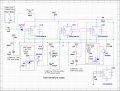
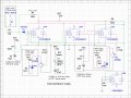
Then I'd use the 4538. You can direct couple the trigger signal and configure as non-retriggerable. That eliminates the OR and NOT gates; providing the current sink capability is sufficient. And voltage levels are compatible.
 

Thread Starter

stillgrowingup

Joined Jul 15, 2015
219
Thank you for the recommendations of the 4538. ... Is the 4538 like a CD4030BE? .. Meaning, I have used a 4030 in a past circuit. The 4030 has gotten warm/hot to the touch and de-bounces often when triggered. Is the 4538 more stable?


TONY
 

Thread Starter

stillgrowingup

Joined Jul 15, 2015
219
For the CD4538 ... Am I to wire one half has Retriggerable Monostables and the other half of the chip has NON-Retriggerable? ... Use "AA" and "AB" input on the chip? ... But "BA" and "BB" to 12V. ... OR NOT output of chip to "B" input if used has Non-Retriggerable. ... Correct?

Thank you

TONY
 

dl324

Joined Mar 30, 2015
18,360
Am I to wire one half has Retriggerable Monostables and the other half of the chip has NON-Retriggerable?
As shown in the diagram in post #16, both oneshots triggered by the PIR sensor need to be non-retriggerable.
Use "AA" and "AB" input on the chip? ... But "BA" and "BB" to 12V. ... OR NOT output of chip to "B" input if used has Non-Retriggerable.
What datasheet are you using? Motorola and NatSemi label the trigger inputs A and B. A triggers on a rising edge and B triggers on a falling edge. What do AA, AB, BA, and BB refer to?
 

dl324

Joined Mar 30, 2015
18,360
Am I to wire one half has Retriggerable Monostables and the other half of the chip has NON-Retriggerable? ... Use "AA" and "AB" input on the chip? ... But "BA" and "BB" to 12V. ... OR NOT output of chip to "B" input if used has Non-Retriggerable. ... Correct?
Understand what the letters designate now, but not sure what you're asking.

To make the oneshots (OS's) triggered by the sensor non-retriggerable, connect the output of the 3-15 second OS to the A inputs of both. I'd attach a schematic, but the symbol in my schematic editor isn't very good. Have no idea why they didn't just do it the way it's done in the datasheets.
 

dl324

Joined Mar 30, 2015
18,360
upload_2018-6-19_16-47-37.png
Additional circuitry required if the output characteristics aren't compatible with the LED controller. You could make the circuit power on in the reset state by adding a capacitor between the reset pins and ground (might need to make R4 100k in that case).
 

Thread Starter

stillgrowingup

Joined Jul 15, 2015
219
View attachment 154740
Additional circuitry required if the output characteristics aren't compatible with the LED controller. You could make the circuit power on in the reset state by adding a capacitor between the reset pins and ground (might need to make R4 100k in that case).
Thank you for the circuit. If I understand the circuit correctly. IC1A is a one shot for the 'ON' output. IC1B is the timed trigger for IC2A to send the 'OFF' output.

Using 10K for R1&R3 and 100uF for C1&C3. Given me a 1 second for 'ON' and 'OFF' output ... R2 will be a 50K variable resistor pot. C2 will be a 330uF. This giving me a times off output upto 18 seconds and lower.

I think I will use a BD140 PNP on the outputs of the CD4538. Just incase. Should I use Diodes anywhere. Or a capacitor across each if the CD4538 Vss and Vdd pins? Should the unused inputs of the 2nd chip be put to GND?

If my thinking is correct. I'll draw something up and post it.

TONY
 
Last edited:

dl324

Joined Mar 30, 2015
18,360
Using 10K for R1&R3 and 100uF for C1&C3. Given me a 1 second for 'ON' and 'OFF' output ... R2 will be a 50K variable resistor pot. C2 will be a 330uF. This giving me a times off output upto 18 seconds and lower.
I'd use the smallest capacitors you can because they'll contribute most of the timing error.

With larger caps, you also need to consider how much filter cap there is in the circuit. When you turn off power, the timing caps will discharge through the input protection diode of the PMOS device. The current needs to be limited to something that won't damage the diode.

With "small" timing capacitances and bench supplies, discharge current isn't usually a problem. With larger caps, you need to address it.

EDIT:
This is probably the easiest way to protect the device during power down; from a Motorola datasheet:
upload_2018-6-21_8-26-3.png
I was inclined to use a resistor between T1 and T2 in series with the cap, but that requires some calculations.

I think I will use a BD140 PNP on the outputs of the CD4538. Just incase.
I think an NPN transistor to the Q output would be more appropriate.
Or a capacitor across each if the CD4538 Vss and Vdd pins?
Decoupling caps are always recommended.
Should the unused inputs of the 2nd chip be put to GND?
From page 4 of the datasheet you're using:
upload_2018-6-21_8-11-45.png

If my thinking is correct. I'll draw something up and post it.
A schematic is always a good idea when discussing circuits. It would also give us a better idea of how you plan to use the transistors; current limiting resistor and whether you have a resistor to limit collector current.
 
Last edited:

Thread Starter

stillgrowingup

Joined Jul 15, 2015
219
I have attached a schematic I made using the understanding I have of the info you have given me. It's probably NO where near correct. LOL.

I searched for other CD4538 circuits and try to compile the circuit I am looking for.

I appreciate your feedback.

TONY
 

Attachments

dl324

Joined Mar 30, 2015
18,360
I have attached a schematic I made using the understanding I have of the info you have given me. It's probably NO where near correct. LOL.
I'd use something like 100k and 10uF for the 1 second interval and 500k and 33uF for the 30 15 second interval. The tolerance of electrolytic caps of those sizes will probably be +/-20%. For those values, tantalum is also an option.

Do an experiment driving your LED controller with typical CMOS outputs before you go to the bother of using external transistors. AT VDD=12V, they'll probably sink/source 2mA.

You have the transistors connected to the wrong polarity output. 100 ohm base resistors will load the timer outputs. The transistors shouldn't have to sink much current. Your experiment driving the controller with a CMOS output will tell you if that's the case.

You can force Multisim to give cleaner routes (i.e. non scenic) by using the shift key.
 
Last edited:

Thread Starter

stillgrowingup

Joined Jul 15, 2015
219
After a few adjustments. This circuit functions in my MultiSim. Breadboard next!! I have to order a few parts first!

I put LEDs in my multisim for visual feedback. Lower the resistance for the one-shot timer to 500mS. (For some reason the LED need a 10 ohm resistor to function in my MultiSim.) I needed to add a pull-up resistor to the trigger input. On U2A, I had to swap the trigger pins. And added the PNP has you suggested. I will try to fire the LED controller without the PNP first with my breadboard test.

Other than Decoupling caps for the CD4538 which are not present on my MultiSim circuit. Is there anything you guys notice I should add to protect either the circuit or the LED controller?

Thank you
TONY
 

Attachments

dl324

Joined Mar 30, 2015
18,360
After a few adjustments. This circuit functions in my MultiSim. Breadboard next!! I have to order a few parts first!
It's confusing for U1B to show power connections that don't need to be hooked up.

The transistor switches are wrong. You want NPN transistors because you want to switch the controller inputs to ground.

A 330uF tantalum with a 15+V rating is going to be big and expensive
 

Reloadron

Joined Jan 15, 2015
7,892
I would like to mount an old Alarm proximity sensor to my front bumper. When something passes near the front of the car. The prox sensor sends out a negative DC ground pulse to turn on the LEDs. Then after a few seconds, between 3 to 15 seconds variable. Another pulse is sent out to turn off the LEDs.
With that in mind your sensor is really designed for interior use. Not to dissuade your plan but you may want to consider just buying a cheap PIR sensor module similar to this one or any of the offerings from Parallax which will sense motion at about 20 feet away. Then follow that up with a simple and inexpensive One Shot Relay Module similar to this one. The One Shot relay modules allow for settable times and ranges using jumpers. While not a MOSFET design the relay will do fine turning the LED strips on and off unless you want any special features your existing controller offers. The total would be likely $20 USD or less for parts.

Ron
 

Thread Starter

stillgrowingup

Joined Jul 15, 2015
219
Hi All

Update. I have breadboard the circuit and after a few more component adjustment. The circuit worked!! I have attached the working circuit to this post. Of course this circuit did NOT work in the multiSim. But did work in real life. :) ... I had to add a R12 (100k) to the timer circuit so that there will always be an OFF pulse, after the ON the pulse. Turning the POT to low, caused the OFF pulse to NEVER emit after the circuit was triggered. Locking the circuit. So now there will also be an OFF pulse 5 second after the circuit is triggered.

I will next remove the LED controller from my car. And try it together. :)

I ask everyone. Looking at the circuit attached to this post. Do you see something I should add in the circuit. For either better operation of the circuit.. OR ... to protect the circuit?

Thank you

TONY
 

Attachments

eetech00

Joined Jun 8, 2013
4,709
Hi

Here is a sim and some suggestions.

I added a diode at the supply input for some reverse polarity protection.
A 100uf cap for some supply smoothing.
An 18v Zener for a little overvoltage protection.
a 0.047u cap for some contact debouncing.
Low power LED indicators (2V,2ma).
Removed PNP's and replaced with small nmos mosfets and current limiting resistors.
All timers are configured as non-retriggerable.
The math says the off-delay timer RC values sets the time range 4.7 to 28.2 seconds.

I don't know what the diode at the input of Q1A is for(?)

eT
 

Attachments

Top