The doubled frequency is NOT the output frequency. It is the frequency that is input to the 50% duty cycle generator. As such, in the proposed scheme for a maximum frequency of 1KHz, one would generate the input frequency of 2KHz. Or a range whose endpoints are double that of the output frequency.
Feed this input frequency into a D flip flop wired as a T (toggle) flip flop. That is, connect notQ output to the D input. Then, the Q and notQ outputs are your alternating outputs.
Much simpler than the circuit you posted. It only used one flip flop.
It would help if you could also generate a timing diagram, so we can validate any suggestions
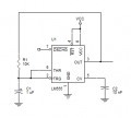
If you want F/2 at (arbitrarily) 0 degrees and 180 degrees, take the signals from IC2A pins 1 and 2. they are complimentary. Tie pins 8, 9, 10, and 11 to GND, and ignore 12 and 13.
Check the 4013 datasheet for its output current ratings, and note that as the output current (either sourcing or sinking) increases, the output voltage margin increases.
It is not so much 0 and 180°, as 90° and 270° (the peak and the trough), but thank you for your help. It is most appreciated.
I'm gonna follow your suggestions tomorrow (it is midnight here).
You are dealing with all square-wave devices and signals, so there are no peaks and troughs in the traditional sense (as with sine waves). The two signals are 180 degrees out of phase with each other, but nowhere in this thread have you indicated that you wanted them 90 degrees phase shifted from the source.
You are dealing with all square-wave devices and signals, so there are no peaks and troughs in the traditional sense (as with sine waves). The two signals are 180 degrees out of phase with each other, but nowhere in this thread have you indicated that you wanted them 90 degrees phase shifted from the source.
Hi,
Yes, I am aware that peaks and troughs do not occur with square waves (I deleted the 'so to speak' after peak and trough in order to shorten the sentence), I was trying to clarify the situation but seem to have failed in that respect and true, it would have helped if I had clarified the phase degree positions, however this thread was started whilst in the hunt for a duty cycle display and has mutated somewhat as it became apparent that a display was not necessary...
The doubled frequency is NOT the output frequency. It is the frequency that is input to the 50% duty cycle generator. As such, in the proposed scheme for a maximum frequency of 1KHz, one would generate the input frequency of 2KHz. Or a range whose endpoints are double that of the output frequency.
Feed this input frequency into a D flip flop wired as a T (toggle) flip flop. That is, connect notQ output to the D input. Then, the Q and notQ outputs are your alternating outputs.
Much simpler than the circuit you posted. It only used one flip flop.
It would help if you could also generate a timing diagram, so we can validate any suggestions
Tried your connection changes and although they are brilliantly simple, they don't seem to work. I only get a frequency from Q once I connect the opto's
If you want F/2 at (arbitrarily) 0 degrees and 180 degrees, take the signals from IC2A pins 1 and 2. they are complimentary. Tie pins 8, 9, 10, and 11 to GND, and ignore 12 and 13.
Check the 4013 datasheet for its output current ratings, and note that as the output current (either sourcing or sinking) increases, the output voltage margin increases.
You've told me that doesn't work. You've rather aggressively told AnalogKid that his suggestion doesn't work.
But you haven't told us WHAT doesn't work. We have no idea what you did. We have no reason to believe that you did what we suggested. What we know is something doesn't work. And we likely believe it's not what we suggested.
Put your image where your mouth is. Post a schematic, or I can't waste any more time on this.
Ok, you can't take a pic. Draw it in MS Paint. Or use an online schematic tool, like https://www.circuitlab.com/ (disclaimer: I have not personally used this tool. Just presenting it as an example of what's available)
I wasn't offended. Just stating that it is difficult/ impossible to help without knowing what you've done.
You mention that you wonder if the pins can pass enough current. Two points. The datasheet will tell you if the pins can pass enough current. The schematic will tell you if you are supplying enough current to the opto.
 Facebook
 Google
 GitHub
 Linkedin

") Good point.
Good point.