Long chain of MAX7219 Matrix displays Fail

Thread Starter

n4mwd

Joined Mar 21, 2016
50
Part of the effect is to introduce a low-pass filter formed by the IC's input capacitance and the resistor. That's often a bad thing to do, but the chip has hysteresis on those inputs so it will tolerate slow transitions with no problem and the clock rate isn't very high.
I neglected to mention that I'm running the CLK at 8MHz. So far, every frequency I've tested (<= 8MHz) has worked flawlessly.
The filter will work from "both sides" of the resistor - if there is noise on the clock it will filter some of that, if the the IC ground bounces (as it will), it will defend the clock input from some of that.
That's what I'm seeing. The resistors filter glitches from the MAX chip to the bus and from the bus to the MAX chip. Its rather amazing the difference it makes.

Also, the last module is now unterminated. At one time I had pullup and pulldown resistors on the signals and caps on the power, but all of that is gone now. The only change in capacitance is that I moved the 10uF and 0.1uF bypass caps closer to the chip. That alone didn't fix anything, but I went ahead and modded all the boards anyway.

Thanks for all your help (and everyone else's too). I know I'm not the only one with this problem because there are threads all over complaining about the problem, but nobody had a real solution - until now.
 

Korede

Joined Jan 9, 2019
7
Hello n4mwd, thank you for this tirelessly effort of yours. I have exactly the same issue you solved. I will be glad to have your email address sir. My own email is <SNIP>. Thank you sir.

Moderators note : removed email to avoid spam
 
Last edited by a moderator:

Korede

Joined Jan 9, 2019
7
What type of modules are you using?
1088as dot matrix display. But I'm still implementing the resistors you included in your design. Please, is your display still working flawlessly till now without that old issue. I mean did the resistors in CLK and LOAD lines solve the problem permanently? Thanks. Having your email too will be good. Thanks.
 

Thread Starter

n4mwd

Joined Mar 21, 2016
50
Please, is your display still working flawlessly till now without that old issue. I mean did the resistors in CLK and LOAD lines solve the problem permanently?
Yes, its still working. I also refresh the display 4 times per second just in case, but it isn't usually needed. The display is about 7 feet long and very solid all the way to the end. The CLK and LOAD bus is driven with a high current buffer and each max chip has the two resistors. The resistor values I chose were arbitrary. You can experiment to find out what values work best for you.
 

Thread Starter

n4mwd

Joined Mar 21, 2016
50
Thanks for your reply. Refresh the display? Is it to shutdown and restart the max chip?
I think you might want to edit your previous post and delete all the extra attachments. The attachment was posted about 20 times.

The refresh code is a left over from when I was trying to get it to work before I figured out to use the resistors. It completely re-initializes the Max chip and then resends the data. I left it in because it is still possible that the MAX chip could get a spurious command to shutdown. Now that I have the resistors, refreshing every minute is more reasonable, but since its not hurting anything, I just left it in.
 

Korede

Joined Jan 9, 2019
7
I think you might want to edit your previous post and delete all the extra attachments. The attachment was posted about 20 times.

The refresh code is a left over from when I was trying to get it to work before I figured out to use the resistors. It completely re-initializes the Max chip and then resends the data. I left it in because it is still possible that the MAX chip could get a spurious command to shutdown. Now that I have the resistors, refreshing every minute is more reasonable, but since its not hurting anything, I just left it in.
Okay. Thank you so much. Please put me through editing my post because I don't know that happened. I only wanted to send once. Thanks.
 

Thread Starter

n4mwd

Joined Mar 21, 2016
50
Okay. Thank you so much. Please put me through editing my post because I don't know that happened. I only wanted to send once. Thanks.
I think the moderator took care of it for you. Sometimes you click it and nothing happens and then you click it again and again and still nothing happens. Then it finally takes it and there are 20 attachments with the same file.

So have you modified your MAX boards to add the two resistors? Did it work?
 

Korede

Joined Jan 9, 2019
7
I think the moderator took care of it for you. Sometimes you click it and nothing happens and then you click it again and again and still nothing happens. Then it finally takes it and there are 20 attachments with the same file.

So have you modified your MAX boards to add the two resistors? Did it work?
Yeah. The two resistors helped greatly. My display is now fine. Thanks a million times. I really appreciate your support.
 

Attachments

Thread Starter

n4mwd

Joined Mar 21, 2016
50
I hope the silicon demons that max chips were possessed that you used the two resistors to cast out will now allow you to use max for future development? Or you were still running away max?
Yes, anybody who makes a MAX display board should incorporate those resistors in each module. I would shy away from the MAX with future designs, but it all comes down to cost. I had previously looked at the Holtek HT1632C which controls four 8x8 matrix displays, but it cannot be daisy chained like the MAX and requires 32 current limiting resistors.

A more stable alternative to the MAX is a Busy Bee EFM8BB31F16G-B-QFP32 which costs about $1 USD and can drive two 8x8 matrices and has an I2C interface. The down side is that it needs 16 resistors and some firmware since its a 50 MHz CPU. But since its I2C, error detection and correction can be added rather easily.
 

Korede

Joined Jan 9, 2019
7
Yes, anybody who makes a MAX display board should incorporate those resistors in each module. I would shy away from the MAX with future designs, but it all comes down to cost. I had previously looked at the Holtek HT1632C which controls four 8x8 matrix displays, but it cannot be daisy chained like the MAX and requires 32 current limiting resistors.

A more stable alternative to the MAX is a Busy Bee EFM8BB31F16G-B-QFP32 which costs about $1 USD and can drive two 8x8 matrices and has an I2C interface. The down side is that it needs 16 resistors and some firmware since its a 50 MHz CPU. But since its I2C, error detection and correction can be added rather easily.
Thanks. I will stick with max for now since the problem is now gone.
 
Hello n4mwd,

I Made a board for our local fire house. I have the same problem. I add a Logic level Swifter to my Raspberry pi project to boost the MOSI SPI and CL. Those are going to the max7219. I have 18 of them.

In your journy to the solution i read you only add 2 resistors for eache module?
Do you have pictures of the resistors?
AACF6164-FA04-45B9-8151-68AF89D94F56.jpeg
I looking forward to see youre sulotion.


Thank you for youre share

Grtz Paul
 

Thread Starter

n4mwd

Joined Mar 21, 2016
50
Yes, just two resistors on each module. They are in series with the clock and latch lines between the bus and the chip. They are not between the bus in and bus out so all modules receive the same signal strength.

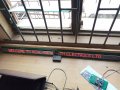
I used a silicon labs 8051 cpu which drives at 3.3V. I don't know what a "swifter" is, but I assume you mean some kind of buffer. I tried that as well and it made things worse. The modules that I used were custom made with each LED soldered independently. There were about 1000 of them in the whole project - literally.

Even with this fix, there are still occasional mangled characters, but I refresh 4 times a second to make it less noticeable.
 
Hello n4mwd, thank you for your effort. I have the same issue you solved on 8 displays i made. The big 8x8 matrixes from Bluino seen on Instructables. Thank you a thousand times. Anybody who makes a MAX display board should incorporate those resistors in each module.
 

Attachments

Top