 Facebook
 Google
 GitHub
 Linkedin
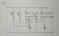
Hi everyone, I wonder if you can help. I am building a half-adder with my class like the one attached, except the ICs only work when fed a switched negative signal, not a positive. I’d like to use TinkerCAD simulation to help the students with design systems, prototyping and circuit design basics, but their simulation only works when the IC is fed a switched input from the positive rail as per the image. I’m not sure whether the problem is me or the system, can anyone help me identify what’s going on? The chips in the simulation are 74HC36’s and mine are 74LS36’s, but from what I can gather it’s only their power characteristics that differ and shouldn’t affect their operation I don’t think? Any help would be gratefully appreciated.
Attachments
-
 763.9 KB Views: 10

")


