Logic gate help

Thread Starter

tankerck09

Joined Mar 29, 2020
4
Hello All,

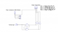
It's been 10+ years and since playing with logic IC's and I have a project that needs some logic for model railway signals. I have 2 input relays and 4 common anode led's to light according to the input from the switch relays. I made a diagram with a truth table. What 7400 series chips should I use?

ps. I could easily do this with a micro-controller but i have tons of IC chips around from the digital electronic days in Grade school.
 

Attachments

ci139

Joined Jul 11, 2016
1,898
\(\displaystyle{\begin{array}{c|c|c|c|c|c}
S_1 & S_2 & L_1 & L_2 & L_3 & L_4\\ \hline
\mathbf{0} & \mathbf{0} & 0 & 1 & 0 & 1\\
\mathbf{0} & \mathbf{1} & 0 & 1 & 0 & 1\\
\mathbf{1} & \mathbf{0} & 0 & 1 & 1 & 0\\
\mathbf{1} & \mathbf{1} & 1 & 0 & 0 & 1\\ \hline
& & {L_1=S_1S_2=\\ =\overline{\overline{S_1S_2}}=\\ =\overline{\overline{S_1}+\overline{S_2}}} & {L_2=\overline{S_1S_2}=\\ =\overline{S_1}+\overline{S_2}=\\ =\overline{L_1}} & {L_3=S_1\overline{S_2}=\\ =\overline{\overline{S_1}+S_2}} & {L_4=\overline{S_1\overline{S_2}}=\\ =\overline{S_1}+S_2=\\ =\overline{L_3}}
\end{array}}\)
you can use LM339 for Resistor-Comparator logic http://tinyurl.com/rsy5dh3 , about (Pg.6 , Fig.11) https://www.analog.com/media/en/technical-documentation/data-sheets/CMP04.pdf
 
Last edited:

crutschow

Joined Mar 14, 2008
34,284
I would use the CD4000 series CMOS gates.
They can operate from 3V to 15V supplies and draw essentially no current in the static state.
 

danadak

Joined Mar 10, 2018
4,057
This is for future consideration.

There is a family of parts where, w/o writing any code, even though it has an arm processor in it,
you can drag and drop gates onto schematic, wire up internally and out to pins. Think of it as a
logic breadboard on a chip. It has a library in tool of basic logic elements, as well as advanced things
like PWM, DSP, Timers, Counters, lots of analog. Also the community of users have created library of
parts like 74 MSI, DDS, that can be added to its design library.

The IDE (PSOC Creator) and compiler free - https://www.cypress.com/products/psoc-creator-integrated-design-environment-ide

Dev board $ 10 -https://www.cypress.com/documentation/development-kitsboards/cy8ckit-059-psoc-5lp-prototyping-kit-onboard-programmer-and

Here is example using LUT that is in logic library. Note this LUT can be configed as registered allowing
state machines to be created. all w/o writing code. Although the other 90+% of chip resources would
be unused. Or I could have done it with simple gates out of the library. I configed LUT to implement your
truth table. Its just point and click to set logic values for input states.


1585492579243.png

The right hand window shows resources used vs left to be used.

Window to its left is catalog of components on the chip you drag and drop onto canvas to
do design. Then wire up with wiring tool, internally and to pins. A component in PSOC is an
onchip resource. Catalog of components for this 5LP family part attached.

Lots of fun, fast turn ideas to actual design.

And if you get into coding tons of advanced components to work with onchip.


Regards, Dana.
 

Attachments

Thread Starter

tankerck09

Joined Mar 29, 2020
4
This is for future consideration.

There is a family of parts where, w/o writing any code, even though it has an arm processor in it,
you can drag and drop gates onto schematic, wire up internally and out to pins. Think of it as a
logic breadboard on a chip. It has a library in tool of basic logic elements, as well as advanced things
like PWM, DSP, Timers, Counters, lots of analog. Also the community of users have created library of
parts like 74 MSI, DDS, that can be added to its design library.

The IDE (PSOC Creator) and compiler free - https://www.cypress.com/products/psoc-creator-integrated-design-environment-ide

Dev board $ 10 -https://www.cypress.com/documentation/development-kitsboards/cy8ckit-059-psoc-5lp-prototyping-kit-onboard-programmer-and

Here is example using LUT that is in logic library. Note this LUT can be configed as registered allowing
state machines to be created. all w/o writing code. Although the other 90+% of chip resources would
be unused. Or I could have done it with simple gates out of the library. I configed LUT to implement your
truth table. Its just point and click to set logic values for input states.


View attachment 202814

The right hand window shows resources used vs left to be used.

Window to its left is catalog of components on the chip you drag and drop onto canvas to
do design. Then wire up with wiring tool, internally and to pins. A component in PSOC is an
onchip resource. Catalog of components for this 5LP family part attached.

Lots of fun, fast turn ideas to actual design.

And if you get into coding tons of advanced components to work with onchip.


Regards, Dana.
I'd like to keep it simple gates. I really don't need feature creeping here or possible future expansions out of this project.
 

danadak

Joined Mar 10, 2018
4,057
Like I said, its strictly for future consideration. Wiring up simple gates very instructive
when you first do stuff. Like building a house before power tools. One can learn a lot
of skills working that way, then as one progresses speed from ideas to fruition become
more important. And of course chip count minimization = more reliability, less power,
less cost.

Regards, Dana.
 
Last edited:

dl324

Joined Mar 30, 2015
16,846

djsfantasi

Joined Apr 11, 2010
9,156
I'd like to keep it simple gates. I really don't need feature creeping here or possible future expansions out of this project.
This is fairly simple with a few CD4000 Logic Gates/ICS.

Just to clarify, your chart has a 0 when the turnout is set for the main; a 1 when it’s set for the siding. Correct?

The siding turnout’s position is displayed how? Is it set to a 1 for the diverging route and a 0 otherwise?

It might be helpful if you marked the logic values directly on your diagram.

As far as the lights, are the relays switching ground or power to each one?

And finally, how will the inputs to the gates be determined? Will there always be a 1 or 0 (that is power or ground) connected to the gates?

Waiting your answers.
 

djsfantasi

Joined Apr 11, 2010
9,156
I've walked away for a bit and came back to it and wired it up first crack... I ended up using 2 IC chips a 74HC00N and a 74HC04N.
By the way, the 7400 has 4 gates. You’ve used two; the other two can be wired as inverters (tie their inputs together) and thus, you don’t need the 7404 at all!
 

djsfantasi

Joined Apr 11, 2010
9,156
By the way, the 7400 has 4 gates. You’ve used two; the other two can be wired as inverters (tie their inputs together) and thus, you don’t need the 7404 at all!
OR, keep the 7404... you have 4 extra gates, which you can connect in pairs and use them as a buffer to drive the LEDs. Thus, not loading the outputs of the NAND gates.

You may need to inventory your power requirements. The chips may not be able to drive the LEDs directly.
 

danadak

Joined Mar 10, 2018
4,057
You simply buffer any signal path where its output is used to both drive a load and
another gate. So in your example above the problem is L3, just use a couple of gates
in series (since they are inverting) to drive LED at their output, while still driving L4
with a non LED signal.

So U2.1 drives U1.1 and U2.2 and U2.1 to drive two series gates out to connector and LED.

You have a similar problem with output of U2.2

I did not check the logic of your wiring, I leave that to you

1585513517757.png


Regards, Dana.
 
Last edited:

djsfantasi

Joined Apr 11, 2010
9,156
You simply buffer any signal path where its output is used to both drive a load and
another gate. So in your example above the problem is L3, just use a couple of gates
in series (since they are inverting) to drive LED at their output, while still driving L4
with a non LED signal.

So U2.1 drives U1.1 and U2.2 and U2.1 to drive two series gates out to connector and LED.

You have a similar problem with output of U2.2

I did not check the logic of your wiring, I leave that to you

View attachment 202848


Regards, Dana.
Exactly what I said in post #13. I knew it was a good idea.
 

dl324

Joined Mar 30, 2015
16,846
@tankerck09 Didn't mean to scare you off. If I understood your requirements, the circuit you proposed wouldn't work; this one will:
1585761128764.png

You still need to avoid loading gate outputs, so buffers would be needed to drive the LEDs.
 
Top