Locking potentiometer? Recessed?

Thread Starter

james211

Joined May 29, 2012
291
The sparkcore's PWM runs at 500Hz, so that should be fine.

After a bit of chatting with the sparkcore's engineers, they lead me to a IRLB8721PbF MOSFET which will work well with the cores 3.3v.

It does need a power cap (470uF) adding between the transistor E pin (gnd) and the red +pwr wire.
In this case should I put the power cap between the S pin and the red +pwr wire?

From a noise viewpoint you could make a couple of tweaks. I would solder the diode directly across the motor terminals to keep PWM recirculating current local to the motor, and I would add a small poly cap from B-E of the transistor (parallel to your 1k resistor).
Since you we had originally talked about using a TIP120, which had a different pinout, would you mind making a suggestions for this new FET?

The diode I'm going to order - IN5819
What small poly cap????
 

THE_RB

Joined Feb 11, 2008
5,438
The TIP120 and all modern nchannel FETS in TO-220 pack have the same pinout. BCE = GDS

Most of the SMD FETs are also GDS pinout, it's a modern standard.

The large PSU cap sould be placed close to the FET and terminals (2 motor wires) since the pulse current for PWM ON is circular;
CAP+ -> motor -> FET Drain -> FET Source -> CAP-

IN5819 schottky is fine.

Re the small cap just use a cheap common poly cap, I'd go 0.1uF or 0.22uF. It's not critical since your PWm is at 500 Hz.

That is with a 4k7 resistor from the sparkcore digital output pin to the FET Gate. That slows down the FET ON/OFF transitions to reduce radiated noise.
 

Thread Starter

james211

Joined May 29, 2012
291
I'm a bit confused by your last paragraph.
That is with a 4k7 resistor from the sparkcore digital output pin to the FET Gate. That slows down the FET ON/OFF transitions to reduce radiated noise.
Right now I have a 330k resistor between the gate and the digital out pin.
 

THE_RB

Joined Feb 11, 2008
5,438
Your schematic says 330 ohm, not 330k! :eek:

You don't need high speed switching, in fact you need the opposite. Change the 330 ohm resistor to 4k7 (4.7k) or similar.

You will also need to change R2 from 1k to 47k or 56k, it's not critical, it's only to keep the FET off if the micro PCB is disconnected (and while the micro boots up).

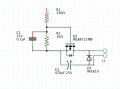
Your circuit seems ok apart from the schottky diode is reversed. The bottom pin of J1 is +PSU, and pin2 of the FET (Source pin) is -PSU or GND.
 

Thread Starter

james211

Joined May 29, 2012
291
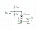
Thank you for the recommendations, and noticing the diode, I switched the layout a bit and forgot to flip that.

Does this look better?

Hopefully I'll have the FET today and be able to test everything this weekend. If this works, I'd like to get a prototype made of this board. Most of the sources I found take about 2-3 weeks, and I really don't want to wait that long. I don't mind waiting once I've confirmed everything is working, but for prototyping I'm a bit impatient at this point as this taking longer than I expected.

Thank you!
 

Attachments

THE_RB

Joined Feb 11, 2008
5,438
Major fail! Now you reversed the FET. :eek:

For prototyping such a simple circuit you can just solder the parts point to point. Or just use 0.1" stripboard or protoboard.
 

THE_RB

Joined Feb 11, 2008
5,438
That was not a criticism! :)

I was commenting to make a point that you had not labeled the +PSU and GND on the schematic.

You're doing well. :)
 

Thread Starter

james211

Joined May 29, 2012
291
So I put the circuit together today with my arduino and a TIP120, I still haven't received my IRLB8721 FETs from Adafruit yet. At first I couldn't get the motor to turn on. So I started pulling and playing a bit, and it turns out its the 4.7k resistor that's between the digital out pin on the arduino and the base pin on the TIP120 FET. I slowly dropped lower resistors in, and it wasn't until I placed a 100ohm resistor that the motor started to run. After a few startup tests I noticed that with the 100ohm resistor in place, the motor starts up slow, without it, its immediately at speed. Any suggestions?

I also don't have any .1uF capacitors yet either, so I'm running the circuit without it.

I'll run some pump tests and see how accurate and consistent it is at low duty without the resistor between the digital pin and the FET. Crossing my fingers!
 
Last edited:

THE_RB

Joined Feb 11, 2008
5,438
The TIP120 is a darlington, and with a typical running gain of over 1000 only needs a VERY tiny base current to operate your 100-200mA motor. The 4k7 resistor is fine.

My guess is that you simply connected it wrong. Please re-check all your wiring or show a clear photo so we can help you check it. :)
 

Thread Starter

james211

Joined May 29, 2012
291
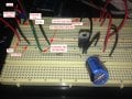
ok, here is a photo, with notes so you know where wires are going to items not on the breadboard. There is a photo attached to the post, I've also attached a zip of a full resolution image in case you needed to have a closer look.

Side notes, I haven't added the 0.01uF cap yet, I'm hoping radio shack will have them and I can pick up today. The diode has been soldered to the motor contacts, so you can't see that either.
 

Attachments

THE_RB

Joined Feb 11, 2008
5,438
At first glance your wiring looks ok, but your resistor from B-E of the transistor looks to be yellow purple black, which is 47 ohms. (Or yel purp brown which is 470 ohms.) That resistor should be 47k, which is yel purp ORANGE.

That's only a thousand times wrong in value, no sweat. ;)

And the small cap should be 0.1uF or 0.22uF, which are very common values. If you have so few parts that you need to be making trips to the store for one common value cap, you should consider buying a heap of assorted values or buying a mixed value pack. Ebay seems to have mixed bags of caps and resistors etc. That may be cheaper than buying a couple of each value as individual parts.
 

Thread Starter

james211

Joined May 29, 2012
291
Just to clarify, the .01uF cap goes between the gate and supply correct?

Thank you for your help.
 
Last edited:

THE_RB

Joined Feb 11, 2008
5,438
Nope on both counts.
The 0.1uF cap goes in parallel with the 47k resistor; between Base and Emitter pins of the transistor (or between Gate and Source pins if you use a FET).
 

Thread Starter

james211

Joined May 29, 2012
291
Got it! That's how I had, was just double checking. It's working like a charm so far. Need to run a consistency test on the pump rates.

I did just order two new pump samples from china, low cost and both are gear driven. One is a standard gear drive the other is a planetary drive.

Hoping for good results from those as they are only $25/ea.

On a side note, since there will three pumps total, but never more than one running at a time, is there anyway to get away with one FET driver but have three different pots?
 

Thread Starter

james211

Joined May 29, 2012
291
So far this circuit has worked the best of any in terms of low duty and consistency, I was able to get down 16.6mL/minute. Prior I was never able to get below 20..thank you!

Now here is the problem I'm running into, because of how cheap these little pumps are, I'm finding that they eventually stall when set at low duty. When this happens my first instinct was to bump the pot a bit, but for some reason the spark or motor, stops responding to the pot. The only way to get it back to normal is to reset the spark core. Is this a circuit issue or a spark PWM issue?


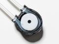
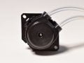
I posted the same question on the spark forum. I'm guessing I need to put these pumps aside in general and wait for the ones from china which actually use gears. These ones just use friction, I've attached a few photos for you to see. Its kind of hard to see, but if you look closely you'll notice there is nothing for the motor shaft to dig into, a gear, or a d-shaft, its just friction.
 

Attachments

THE_RB

Joined Feb 11, 2008
5,438
1. Nope you can;t use one FET to control the speed of 3 motors at once. :)

2. It's normal for the motor to stall at low speeds. It helps if you reduce the PWM frequency. Drop to 200 Hz if you can.

3. Regarding the sparkcore PCB hanging, try putting a large cap (470uF?) across its 5v power pins.

4. Regarding the gearing, the best type of pump is one that uses more gearing. That allows you to run the motor itself faster (compared to pump RPM). And the faster the motor runs the more stable the motor RPM will be from a fixed PWM.

Looking at that pump the gear ratio is quite low, based on the motor shaft diameter and the outer circumference, about 14:1 or so. To get great low speed performance you need much higher gearing than that.

You are using a regulated voltage PSU for the motor power? What are you using for the Sparkcore PCB power? Maybe a photo of the whole setup will help?
 
Top