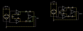
As for the bridge excitation, I'm open to any suggestions. I have a very stable 24V source and unstable 12V battery as voltage sources within my PLC. These are my only supplies that I have at my disposal within my PLC.
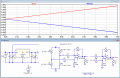
Would making a voltage divider to step down the 24V to 10V be okay for the 10V reference? I believe I could get a 7812 regulator if not. And I have 10 LM358's on hand.hi C,
Are you able to get the 10V reference suggested by Ron, if not can you at least get a 7812 regulator.
Also how many LM358's do you have available.?
E
@danadakLooking at CM error using 1% Rs, only one R swept results in as much as 12 mV
offset. I think had I done all 4 R, by superposition that would result in 48 mV of error.
I then swept the + supply, got another 4 mV of error. These errors pretty much gone
if you use a factory IA (which are laser trimmed).
View attachment 181984
Regards, Dana.
It seems to me that the 1.8K resistor in your "bridge driver" serves no purpose.Is this better?
View attachment 182042
There are literally dozens of 10 volt reference chips out there like this one for just such purposes. A simple Google of 10 Volt Reference chips will give you plenty of results for chips which are designed for exactly your application. The stability of your excitation voltage is a key to both accuracy of the bridge and eliminating drift.Okay. I only have the one 24V supply sadly.
I had totally forgotten about voltage reference chips. I took your advice about the 10V reference chip for excitation of the load cell. I'm also looking at using the INA116 instrumentation amplifier (http://www.ti.com/lit/ds/symlink/ina116.pdf). The gain would be controlled by the value of an external resistor Rg. I calculated that my new maximum output signal from G of the load cell would be 30 mV. With this, my new desired gain value would be 41.666; using this value, I determined Rg should be a 1.3 kohm resistor, which means my gain would be reduced to 38.46 (which is still an acceptable gain for my purposes).There are literally dozens of 10 volt reference chips out there like this one for just such purposes. A simple Google of 10 Volt Reference chips will give you plenty of results for chips which are designed for exactly your application. The stability of your excitation voltage is a key to both accuracy of the bridge and eliminating drift.
Next you want to use a good and highly stable IA (Instrumentation Amplifier, an IC designed around your intended application. I suggest you start by using a Google of instrumentation amplifiers. You can find good amplifiers designed for exactly what you wish to do with programmable gain. You can set the gain for whatever you want very simply and with a good IA low noise and distortion which is what you want along with little to no drift. They require a minimum of external parts.
You have a 5K Lb load cell with a full scale out of 3.0 mV/V so using a nice stable 10 Volt excitation reference with a 5K Lb load applied you get 30 mV out. You are using the load cell in a compression mode only so any good IA can easily be employed. Using a resistive divider as the excitation is a poor choice which will create problems with the design in the end result.
Every PLC I have worked with allowed programming so any analog input could easily be programmed to the engineering units of the users choice. I have no idea what PLC you are feeding or why you want a specific voltage in for a given weight (force) applied to your load cell(s) but with a simple programmable IA you can have whatever you wish. Additionally vendors like Omega who you bought the load cell(s) from even offer amplifiers designed for use with their load cells or any other load cell.
Look at the accuracy of your load cell or better said the overall uncertainty. I am sure you purchased it with the uncertainty in mind. Next look at how you amplify the load cell output and consider that uncertainty. Finally look at the combined algebraic uncertainty of your entire system. How good is it and how good does it need to be?
Ron