Load Cell Output Signal Amplifier Design

Reloadron

Joined Jan 15, 2015
7,891
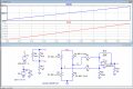
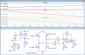
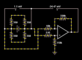
In addition to Dana's fine advice and employing the use of an instrumentation amplifier I see your voltage divider being used to provide the excitation voltage to your load cell. Since the output is a function of the excitation voltage (mV/V) you want to make absolutely sure that your excitation voltage is stable. Less the IA you may want to measure the load cell output with a known load and observe the output over a period of time to make sure it is stable and remains stable. Another forum member has a quite lengthy thread on the subject including maintaining a good zero with the amplifier over time. You can read the thread here.

Ron
 

Thread Starter

Czexican1329

Joined Apr 23, 2018
57
What I'm trying to accomplish is this:
  • I have a balance beam assembly that has two of the Omega load cells on each side.
  • Each pair of load cells will attach to the end of a long object that will act as a load.
  • I want to be able to measure the strain/load on each side of the object when the beam is level or tilts to one side or the other.
  • The load cells each have an output signal of 3 mV/V (3 mV per V of input voltage) that is measured from the green wire (G) of the load cell to the white wire (W) of the load cell; so I want to amplify each load cell's output signal.
  • The max voltage I want to read from the amplified output signal (at max load) is 1.25 V.
  • Because the circuit of the load cell is a wheatstone bridge and I want to measure the difference in voltage between the white wire (W) of the load cell and the amplified output signal (rather than the voltage between the amplified output signal and ground), I now understand that I need to design my op amp circuit as a differential amplifier.
  • Last I knew, I wanted my amplification value (A) to be about 31 to 34 (this may be wrong with these new developments).
So now I need help understanding how to design the differential amplifier circuit and whatever else may help me.

Thank you all for your quick responses and advice. I really appreciate your help!

EDIT: My PLC will be monitoring the voltage between the amplified output signal (the output of the LM358M) and the white wire (W) of the load cell. +/-1.25 V is the lowest range the analog inputs of my PLC can read.
 
Last edited:

ericgibbs

Joined Jan 29, 2010
21,453
hi,
This is a diff amp simulation. [R2 is been increased from 350 R to 351R over the sim plot]
Shows the Vbridge out, the OPA out and the W wrt to 0V.
Note the flat response close to zero for low level signals, this is due to using a single OPA supply voltage.

BTW: at 3mV/V and the Vext at 13.3V [ as per your circuit] , thats a 13V * 3mV = ~40mV for a full load.

What bridge out voltage are you designing for.?

E
Bridge18a.PNG
 

Thread Starter

Czexican1329

Joined Apr 23, 2018
57
hi,
This is a diff amp simulation. [R2 is been increased from 350 R to 351R over the sim plot]
Shows the Vbridge out, the OPA out and the W wrt to 0V.
Note the flat response close to zero for low level signals, this is due to using a single OPA supply voltage.

BTW: at 3mV/V and the Vext at 13.3V [ as per your circuit] , thats a 13V * 3mV = ~40mV for a full load.

What bridge out voltage are you designing for.?

E
View attachment 181925
By bridge out voltage, are you referring to the unamplified output signal measured between G and W or the amplified output signal measured between the output voltage of the op amp and W?
 

ericgibbs

Joined Jan 29, 2010
21,453
hi,
You say in post #22 you want 1.25V at the LM358 output, so I want to confirm the required OPA gain.

Another point to consider is the take off point of the 'W' wire, what impedance will it be driving into.?
E
 

Thread Starter

Czexican1329

Joined Apr 23, 2018
57
Okay. I said that wrong back in Post #22. +/-1.25 V is the lowest range that the analog inputs of my PLC can read. The amplified output signal (output of LM358N) will be connected to the positive analog input, and W will be connected to the negative analog input. As such, the max voltage I want to read between the two analog inputs is 1.25 V.
 

ericgibbs

Joined Jan 29, 2010
21,453
hi C,
I assume you realise that you cannot get a -1.25V output from the circuit when using only a single positive LM358 supply voltage.?
 

ericgibbs

Joined Jan 29, 2010
21,453
hi,
This sim uses all 4 elements of the bridge, a 1 Ohm increase/decrease of the bridge resistors, the Vout is approx 0.1V thru 1.3V.
You will not get a 0V out from the LM358 will a single voltage supply.
Is this circuit getting close to what you have planned.?
E
 

Attachments

Thread Starter

Czexican1329

Joined Apr 23, 2018
57
hi,
This sim uses all 4 elements of the bridge, a 1 Ohm increase/decrease of the bridge resistors, the Vout is approx 0.1V thru 1.3V.
You will not get a 0V out from the LM358 will a single voltage supply.
Is this circuit getting close to what you have planned.?
E
Yes, but V(G,W) should be about 1.25V, not Vout.
 

ericgibbs

Joined Jan 29, 2010
21,453
How can V(G,W) be 1.25V, when using a 13Vext and a bridge with a specification 3mV/Vext...???

There seems to be some confusion, please post your latest diagram

BTW: Is this a College or Homework assignment.?
 

ericgibbs

Joined Jan 29, 2010
21,453
It will not work as you are expecting, as I have said on a number of occasions.

BTW: Is this a College or Homework assignment.?
 

Reloadron

Joined Jan 15, 2015
7,891
The load cell you are using has an output of 3 mV/V ±0.0075 mV/V. The load cell is rated at 5K Lb or 5,000 Lbs.

Your excitation consist of two 470 Ohm resistors in parallel (235 Ohms) in series with a 1.8 K Ohm resistor so Rtotal for your divider is 1800 + 235 = 2035 Ohms. As drawn the divider Vout will be 21.228 Volts as referenced to common. The Maximum excitation for the load cell should not exceed 15.0 volts per the data sheet.. This is what I see.
VoltDiv.png

Just as an example using a nominal 10 Volt excitation and a load cell sensitivity (output) of 3.0 mV/V that tells me at full scale force applied (5,000 Lbs) your load cell would, in this case, output 3.0 mV/Volt of excitation and with 10 Volt excitation that would give me 30 mV out. When you use an excitation anything above the max in this case 15 V you will start heating the bridge and even if you do not destroy the cell it will start drifting because of thermal heating effect of the bridge.

Am I not reading this correctly as to excitation voltage?

Ron
 

ericgibbs

Joined Jan 29, 2010
21,453
hi Ron,
I measure Vext as ~13.3V with the bridge connected across the 1k8.
The individual 350R elements are dissipating about 125mW each

Its a poor way of supplying a bridge.
I have tried advising the TS, to no avail.

Eric
 

Attachments

ericgibbs

Joined Jan 29, 2010
21,453
hi C,
I enjoy helping you, so don't give up.
If you carefully answer any questions I ask, it makes it easier for us to help you.

What help do you need to complete your project.?
E
 

Reloadron

Joined Jan 15, 2015
7,891
measure Vext as ~13.3V with the bridge connected across the 1k8.
The individual 350R elements are dissipating about 125mW each

Its a poor way of supplying a bridge.
I have tried advising the TS, to no avail.
Oh man, my bad on that note but I have to agree I would not excite a bridge in that manner. There are precision 10 volt regulators designed around bridge excitation. They are inexpensive and easy to use as well as providing the stability you want with a load cell.

Ron
 

Thread Starter

Czexican1329

Joined Apr 23, 2018
57
Thank you. I have a load on one load cell and I measured 1.1 mV between G and W of the load cell. I did some calculations and determined that at max load, I want to read about 1.25 V between LM358 output and W, with about 39.75 mV being the max output signal (G) from the load cell at max load. So I calculated that with my current load on the load cell and 1.1 mV between G and W, I should read about 34.59 mV between LM358 output and W. As such, I designed a rough differential op amp circuit to give me about 34.47 mV between LM358 output and W.
upload_2019-7-18_12-26-20.png
Does this make more sense?
 

Attachments

Top