Load Cell Output Signal Amplifier Design

Thread Starter

Czexican1329

Joined Apr 23, 2018
57
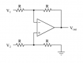
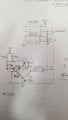
Hello. I've designed an non-inverting op amp circuit to amplify the output signal of a load cell, as the output signal of the load cell is only 3 mV/V. The load cell is an Omega LC101-5K S-beam load cell (https://assets.omega.com/pdf/test-and-measurement-equipment/load-and-force/load-cells/LC101.pdf); and the op amp is an LM358N (http://www.ti.com/lit/ds/symlink/lm358-n.pdf). I will attach photos of my calculations and circuit schematic below. The circuit of the load cell is a wheatstone bridge circuit, which was verified by a representative of Omega. I'm using a 24V source, and the white wire of the load cell (W) is isolated (as the rep told me to do).
According to my calculations, 1.25 V is what I want for Vout, and amplification (A) should be around 31. The unamplified output signal (the green wire or G) from the load cell was measured as 1.1 mV, measured between the green (G) and white (W) wires of the load cell. When I measured the voltage between the white wire (W) of the load cell and Vout (the amplified signal), I instead measured 5.54 V, rather than the 1.25 V I expected. However, I'm reading about 1.34 V between Vout and ground, which is what I thought I should be measuring between Vout and the white wire (W) of the load cell. Am I measuring from the voltages at the correct locations or am I missing something?
 

Attachments

Thread Starter

Czexican1329

Joined Apr 23, 2018
57
hi 1329,
Why have you chosen the VERY low values of Rin and Rfb for the LM358.
E
According to the equation for amplification, A = 1 + Rfb/Rin, 33 ohms and 1 ohm give me an amplification of 34, which is close to the amplification of 31 that I wanted. I had to go with standard values for my resistors. Also, my resistor values are very low because the output signal from the load cell is only 1.1 mV with the weight I have attached to it (about 75 lb), and I want to boost it to about 1.25V.
 

ericgibbs

Joined Jan 29, 2010
18,841
hi,
Where is the W wire from the bridge referenced to, for the LM358.?
E

EDIT:
I will draw a LTSpice sim of your circuit.
 

ericgibbs

Joined Jan 29, 2010
18,841
hi,
This is your circuit, where is W connection point on the LM358.?
E

EDIT:
If W is floating note the OPA Vout for no signal from the bridge, ie: balanced.
 

Attachments

Thread Starter

Czexican1329

Joined Apr 23, 2018
57
Okay. I will look into that. As for the reference when measuring Vout, the way I want the it to be measured is Vout versus W, as the LM358 Vout will be connected to a positive analog PLC input and W will be connected to a negative analog PLC input. My PLC program will be looking at the voltage between these two inputs to determine what the program does next.
 

danadak

Joined Mar 10, 2018
4,057
When you build an IA from scratch there are some serious issues to getting good CM
(Common Mode) performance. Load cell signals are very low, needing high G to get
usbale signals to work with, therefore need amps with great CM performance.

Here is a sim showing just how important R matching and Aol differences are in
CM results -

upload_2019-7-17_15-11-11.png

I would advise you use an IA, they are laser trimmed at factory to get the CM
performance one needs for most bridge designs.


Regards, Dana.
 

TeeKay6

Joined Apr 20, 2019
573
I'm pretty sure I'm not using common mode.
Your circuit presents a case where a common mode voltage interferes with operation; it's not something you choose. [search for "what is common mode voltage?"] The circuit you showed for a differential amp is the correct class of circuit but a very simple version. As @danadak notes, the problem with DIY differential amps is the need for very stable and closely matched resistances. The performance of commercial instrumentation amps (i.e. differential amps) will almost always be far better than you can achieve DIY. There are other possible solutions, but they are all more complicated than using an instrumentation amp.
 

Thread Starter

Czexican1329

Joined Apr 23, 2018
57
So how I described how my load cell will be connected to my PLC, would I want my op amp to be common mode or differential? From what I understand, I want my op amp to operation as a differential amplifier. Which means I need to redesign my op amp circuit. This is where my confusion lies: in how to design the differential op amp circuit.
 
Top