I do see the circuit of the amplifier and I did also see the connections information for the load cell.
BUT, as I anticipated, not a single word as to the required supply voltages, or the correct power supply connectionsare supplied with the product.
The total lack of any useful application information with the product is a huge fatal fault of these on-line vendors. and it appears that the TS did not use any of the provided information except on the sales page.
The connections on the input side are for both amplifier and load cell, with a ten ohm series resistor in the V+ supply line.
Those connections on the output side ARE NOT for a power input connection, but rather for connecting an additional capacitor to filter the negative supply voltage
So it looks to me like that U1, is a 7660, a negative voltage supply device. So quite possibly connecting a positive 9 volts did some damage to the module.
So probably the instrument amp module is damaged. Certainly it needs to be tested to verify that it is not damaged.
So the information is only provided on the sales page. Yes, it is fairly detailed, but it may not have been copied and saved by the TS. And certainly without that information and a fair amount of technical insight, success is not likely.
Hi,
If he wires it as per that image as I posted, it should work.
E
Clip from eBay.
Input voltage: 3-12V DC
Signal output range: ± (Vin-2V)
Negative voltage output: higher than -Vin. As the negative voltage chip output resistance problem, the actual output is higher than -Vin, the greater the load power, the greater the negative voltage drop
1. Wide supply voltage range: the AD620 amplification of this product can be amplified microvolts, millivolt, compared to LM358 amplification accuracy, better linearity, the maximum voltage output range of ± 10V.
2. Magnification range: magnification up to 1000 ti2mes, only through a potentiometer can be adjusted.
3. Adjustable zero through the zero potentiometer to adjust the zero, improve accuracy, there will be no zero drift phenomenon to meet customer needs. 4. A negative voltage output: the module uses 7660A chip output negative voltage (-Vin), can be provided to the customer to drive other dual power load.
5. Mini type: evenly distributed around the four 3mm positioning holes, both sides of the port 2.54mm standard pitch pinhole.
I've found a local guy who has volunteered to help. If I have to I'll pay him to solder the amp onto a breadboard and all I need to do is move pins around. I've realized once it's working I could leave out the aluminium bar and attach the bare cell to a violin bridge. That has all sorts of interesting outcomes. Still, I've paused till the new AD620 arrives. Although folks, could you recommend a not too expensive meter that could measure the un-amplificated load cell output?
Hi S,
An LC of that type will most likely give a 10mV when a 2kG load is applied, when the cell is powered from 5V.
A closure force has to be applied between the fixed LC base and the free end of the LC.
Usually but not always. It is an arrangement of FOUR strain gages in a manner so that for any intended strain two of the gages increase i resistance as the other two decrease. That is why it has four leads and looks like a bridge circuit, because mostly it is a bridge.
I'm back. So my weight scale display arrived today. I can now see my load cell working using the data from an HX711. Can I get a voltage out of the setup to operate a vco? I'm still having no luck with instrumentation amps. Thanks
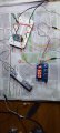
Most load cell calibrations have two adjustments, zero and span. The "ZERO" adjustment is how the static output is nulled out, then the "SPAN" adjustment sets the output based on a known force being applied. The adjustments may also be identified as offset and gain. They are not readable on the image of the module showing in post #39
 Facebook
 Google
 GitHub
 Linkedin