Load cell instrumentation amplifier

Thread Starter

steverod

Joined Jul 11, 2024
48
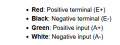
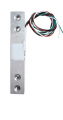
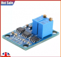
Hi. I know pretty well nothing about electronics. I connected this load cell to this instrumentation amplifier and expected to see some response from my meter when I put pressure on the load cell. I get nothing at all. Am I doing something wrong? What input instead of the load cell could I use to test the amplifier? Many thanks.
 

Attachments

crutschow

Joined Mar 14, 2008
38,430
Am I doing something wrong?
Quite likely.
But that's the only answer I can give, since you haven't shown how the loadcell is connected to the amp and the voltages powering the amp.
My crystal ball is in for repair. :rolleyes:

Since you are new to electronics, you need to know that the language of electronics is schematics.
Never start an electronics inquiry without one.
 

Thread Starter

steverod

Joined Jul 11, 2024
48
Thanks for the quick reply. I was just about to edit that I used a 9v battery for the amplifier and a 6v DC supply for the load cell. The wiring was as advised.
 

Thread Starter

steverod

Joined Jul 11, 2024
48
I have no schematic. Here's the ebay page: https://www.ebay.co.uk/itm/315440643772 I assume the VOUT and GND go to the meter. The Vin and GRN are the 9v feed and the S+ and S- are the signal from the load cell. The load cell is Red E+, Black E-, White A- , Green A+. I believe the E+ and E- are the excitement voltage (6V) and A- and A+ the signal out.
 

LowQCab

Joined Nov 6, 2012
5,101
A Load-Cell, and a matching Amplifier, is not a good first-project.

Unless You are genuinely interested in putting in the years of time required to learn Electronics,
most DIY Electronics-Projects are going to remain out of your reach.

Do whatever it is that You know how to do best to make more Money,
and then purchase a Commercial-Product.

There's a good chance that You don't really need a Load-Cell in the first place.
What is the overall end-goal of having a Load-Cell ?
Why do You think You need one ?

There may be other methods of accomplishing the same end-goal,
and there's a lot of experience here in these Forums that is free for the asking.

.
.
.
 

Thread Starter

steverod

Joined Jul 11, 2024
48
As a violin teacher I want to measure the force used by individuals on their bows. i've dismantled a kitchen scales and mounted the load cell onto a practice violin (nylon roller instead of strings). i get a very useful numerical readout but would like to send the signal to a VCO instead.
 

LowQCab

Joined Nov 6, 2012
5,101
My personal opinion on this is that learning a Musical-Instrument is never going to be made "easy".
If the Student is not really interested in learning that particular Instrument, they will just waste your time.
If the Student is truly interested in learning that particular Instrument,
he will find a way come hell or high-water.

I also think that the most valuable teaching-aid is your personal attention to that Student,
and transferring your valuable experience to them.

I also think that some people are legitimately "Tone-Deaf" and can not be helped.
My oldest Step-Son is Tone-Deaf,
he can not identify the difference between 2 very dissimilar notes,
other than one seeming to be "louder" than the other one, very strange.
While on the other hand, I can keep perfect-Time, and have Perfect-Pitch, with zero "training".

Go-Figure ...........
.
.
.
 

sghioto

Joined Dec 31, 2017
8,634
Thanks for the quick reply. I was just about to edit that I used a 9v battery for the amplifier and a 6v DC supply for the load cell. The wiring was as advised.
Have you tried adjusting the pots?
One is for gain with the 104 number on top.
Typically the output from those type load cells is 2mv per volt of excitation, which means only 12mv at max load.
Would need a gain of at least 10 to see anything on the meter.
Also the negative side of the load cell E- should connect to ground on the amp.
Can you post a close up photo of how you have everything wired?
 
Last edited:

MisterBill2

Joined Jan 23, 2018
27,374
When a load cell is connected correctly to both an INSTRUMENT amplifier and excitation, and no force is applied, the output is usually about zero. Than when force is applied the output goes either positive or negative. So with zero force you should get zero out. That is how they work. By Instrument Amplifier I mean an amplifier with two inputs with close to the same gain from each, except one is inverted. That is, an actual INSTRUMENTATION amp.
An amplifier with an unbalanced input will simply not work at all, and might result in the destruction of the strain gage.

And unlike some others I am usually able to visualize a circuit, given a reasonably coherent textual description. That comes from being able to focus my attention.
 
Last edited:

ericgibbs

Joined Jan 29, 2010
21,421
Hi Steve,
Connect the project as per this image.
Note:
The two Pots, One is Zero offset for the Vout
and the other is the Gain of the Amp. I would say the 104 value pot is the Gain

Use the same 6V for the module and the LC as shown.
When connected, post what you measure.
E
LoadCell1.gif
 
Last edited:

ericgibbs

Joined Jan 29, 2010
21,421
Hi S,
When all connected, place the LC on a flat surface and use hand pressure to press the free end of the LC down, note the change in Vout from no pressure to applied pressure.
Note the Vout maybe a negative voltage when no pressure.

On board the module is a 7660 IC which is positive to negative convertor, as the AD620 requires a +/- Voltage supply.
Post what you measure
E
 

Thread Starter

steverod

Joined Jul 11, 2024
48
Adjusting the pot I can get a constant 1v out but not really anything else. I've tried a different LC with no change. I'll order another amp and try again. I assume it's easy to damage a component when soldering?
 

Thread Starter

steverod

Joined Jul 11, 2024
48
Thanks for that but I'll try again on the new module when it arrives. Any advice on how to solder without damage would be gratefully received.
 

MisterBill2

Joined Jan 23, 2018
27,374
Soldering to a bare load cell element is very critical and needs to be done rapidly with a minimum of heat applied. So a small tipped iron and quite thin wire, #28 stranded, with the wire end tinned prior to soldering to the load cell, works best. But as we have no hint as to what the load cell looks like I have been referencing the ones I saw 20 years ago. The load cell manufacturer should have soldering suggestions available.
But if the cell has leads attached already that is a much better situation.
 
Top