Load cell drift over time

Thread Starter

Bloctopus

Joined Dec 28, 2017
9
Hi AAC,

I have spent the past few days looking through this forum to try and find the problem I am having with my Load Cell boards but am not 100% sure how to confirm that the issue is something like load cell temperature drift.

The issue I am having is that after an hour+ (sometimes 2-3 hours) certain load cells inputs are drifting and reading a lower value that they are starting off with. As soon as the board is re powered everything reads normally again.

I have several of these boards made with only 1-2 boards that do not show this problem.

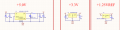
Below is a snip of how my circuit currently looks.

upload_2018-1-2_11-12-58.png

The 1.25V ref is taken from the 5V source

thank you
 

Thread Starter

Bloctopus

Joined Dec 28, 2017
9
upload_2018-1-2_13-29-34.png

The 1.25VREF is outdated as we found that the accuracy off the REF3012AIDBZT in different temperature was not what we wanted.
We then opted for a voltage divider from the 5V line to get our 1.25 reference voltage. But it did not help.


The mV/V varies from our test bench 2mV/V max 50kg to 1.433mV/V max 13,000kg in real applications.

The resolution we want is simply just the best we can get with our hardware. As long as the values do not drift where the "zero" changes.

upload_2018-1-2_13-28-22.png
The values above are monitoring 4 Load Cells (2mV/V max 50kg) over time in uV.
The values are not too bad themselves, there is a clear drift going on , and when dealing with 1000kg's at a time, and multiple load cells, those values are very obvious to the user.
 

Attachments

GopherT

Joined Nov 23, 2012
8,009
That is your zero drift but how many counts are you measuring? 24 bit? 5 count drift on a 16777216 count scale ain't a big deal. Commercial weighing only has to be within 0.5%.
 

joeyd999

Joined Jun 6, 2011
5,287
View attachment 142870

The 1.25VREF is outdated as we found that the accuracy off the REF3012AIDBZT in different temperature was not what we wanted.
We then opted for a voltage divider from the 5V line to get our 1.25 reference voltage. But it did not help.


The mV/V varies from our test bench 2mV/V max 50kg to 1.433mV/V max 13,000kg in real applications.

The resolution we want is simply just the best we can get with our hardware. As long as the values do not drift where the "zero" changes.

View attachment 142869
The values above are monitoring 4 Load Cells (2mV/V max 50kg) over time in uV.
The values are not too bad themselves, there is a clear drift going on , and when dealing with 1000kg's at a time, and multiple load cells, those values are very obvious to the user.
The 4 channels on the 1243 are identical and you show drift on only three of them. The problem is in the amps or the load cells.

Why are you using the amps? The 1243 works exceptionally well with the cells tied directly to it. Heck, you could run the whole thing on 3.3V (including the load cells) -- eliminate the 5v regulator and reference -- and likely get superior performance.
 
Last edited:

Thread Starter

Bloctopus

Joined Dec 28, 2017
9
***0.059mV value in my table above is a typo of 0.050mV***

I am measuring 24bits with the ADS1243 including negative voltage, so really a 23bit +FSR. PGA = 1 (we had problems with the gain impedance effecting the load cells).
Giving me 23bits over 0V -> 0.625V

Gopher; I am worried that if i have 8 load cells connected and are all drifting by 0.005mV each, the sum could be very noticeable.
Also the drift seems to have too much of a pattern. Giving me hope for a fix.
 

GopherT

Joined Nov 23, 2012
8,009
***0.059mV value in my table above is a typo of 0.050mV***

I am measuring 24bits with the ADS1243 including negative voltage, so really a 23bit +FSR. PGA = 1 (we had problems with the gain impedance effecting the load cells).
Giving me 23bits over 0V -> 0.625V

Gopher; I am worried that if i have 8 load cells connected and are all drifting by 0.005mV each, the sum could be very noticeable.
Also the drift seems to have too much of a pattern. Giving me hope for a fix.

Check your board for a poor connection on the affected channel. One trace may be high resistance (overly etched and narrow) or a bad solder joint to a cap.
 

Thread Starter

Bloctopus

Joined Dec 28, 2017
9
The 4 channels on the 1243 are identical and you show drift on only two of them. The problem is in the amps or the load cells.

Why are you using the amps? The 1243 works exceptionally well with the cells tied directly to it. Heck, you could run the whole thing on 3.3V (including the load cells) -- eliminate the 5v regulator and reference -- and likely get superior performance.
Hi, this project was passed onto me from someone else and I did also wonder the same thing when I looked at the design.
But from what I have gathered was that there was a huge problem with the impedance on the ADC as it was halved whenever we cranked up the gain. With the lower impedance this causes a voltage drop on the input which caused us to read lower then the actual voltage.
It all became a balancing act.. so we opted for an external amp.

Now that I am revisiting this thought, I am wondering if the a temperature from a component is messing around with this.
 

joeyd999

Joined Jun 6, 2011
5,287
Hi, this project was passed onto me from someone else and I did also wonder the same thing when I looked at the design.
But from what I have gathered was that there was a huge problem with the impedance on the ADC as it was halved whenever we cranked up the gain. With the lower impedance this causes a voltage drop on the input which caused us to read lower then the actual voltage.
It all became a balancing act.. so we opted for an external amp.

Now that I am revisiting this thought, I am wondering if the a temperature from a component is messing around with this.
What's three load cell output impedance?
 

Thread Starter

Bloctopus

Joined Dec 28, 2017
9
Check your board for a poor connection on the affected channel. One trace may be high resistance (overly etched and narrow) or a bad solder joint to a cap.
This is actually on top of my list of what I think is happening. Each board I have has different cells failing, no real pattern at all.

What's three load cell output impedance?
Sorry. I am not sure as we use different load cells, and this is happening for all of them.
 

joeyd999

Joined Jun 6, 2011
5,287
...and this is happening for all of them.
I find it suspicious that the original output resets itself after re-powering. If the cells are creeping or drifting, they should power back up to the same value.

This makes me think the error is either in your software, or in the auto-zero function of the amps.

Can you restart your data acquisition without powering down the amps? Can you find a way to power down the amps momentarily while keeping everything else running?

Also, you can try to cycle power on only the load cells.

Are you using the auto-calibration feature of the ADS1243? If so, how have you implemented it?
 

Thread Starter

Bloctopus

Joined Dec 28, 2017
9
Joeyd,

I have removed the amps completely and am still seeing this drift.

upload_2018-2-6_10-15-55.png

The bottom line is in seconds. It is kind of hard to see but at the end there I re-powered the board and it jumps back up to its original value.

The SELFCAL is only called on boot and not called again - Would it be worth having this calibration run every few minutes?

Also I have noticed that my 1.25V line (replaced the reg with a divider) is still experiencing some phantom square wave noise on it which I had thought was caused by the regulator.

I will try and power cycle only the load cells next.

thanks!
 

joeyd999

Joined Jun 6, 2011
5,287
Joeyd,

I have removed the amps completely and am still seeing this drift.

View attachment 145260

The bottom line is in seconds. It is kind of hard to see but at the end there I re-powered the board and it jumps back up to its original value.

The SELFCAL is only called on boot and not called again - Would it be worth having this calibration run every few minutes?

Also I have noticed that my 1.25V line (replaced the reg with a divider) is still experiencing some phantom square wave noise on it which I had thought was caused by the regulator.

I will try and power cycle only the load cells next.

thanks!
~7 days worth, huh? Wow. What's the test environment look like?

Off the top of my head, I would suspect very long-term reference drift. Can you run something similar, but with the reference removed (run the reference ratiometrically w/respect to the load cell excitation voltage).

Other than that, I am completely mystified (I would have expected to see daily periodic variations based upon day/night environmental changes if temperature were an issue.)

BTW, the reset level at the end is considerably higher than the signal level at the start. So it did not restore to the same value.
 

cmartinez

Joined Jan 17, 2007
8,257
Exactly the same phenomena happened to me a while back. And I haven't been able to explain it either.

What can you tell us about the circuit's PCB and its layout? Single sided? Double sided? How many copper layers does it have?
 
Last edited:

joeyd999

Joined Jun 6, 2011
5,287
Also I have noticed that my 1.25V line (replaced the reg with a divider) is still experiencing some phantom square wave noise on it which I had thought was caused by the regulator.
I just re-read this. OK, so you are running ratiometrically.

The "square wave" (what amplitude? And what are the values in your divider?) is likely caused when the reference voltage is switched in by the A/D. A 0.1uF in parallel with a 1.0uF cap should eliminate that if that were the case. Is the same square wave apparent on the power supply (use a scope with high-gain on AC setting)?

Regardless, the drift is asynchronous and resettable. So, I'm still at a loss.
 

Thread Starter

Bloctopus

Joined Dec 28, 2017
9
~7 days worth, huh? Wow. What's the test environment look like?
~14 hours actually - left it on overnight.

I would typically see drift happen at the 1-2 hour mark. But have also seen it happen 4-6 hours before.

Here is another diagram with amps
upload_2018-2-6_11-17-12.png
It starts at the 66 min mark and then drifts for 2 hours before settling.

Power cycle towards the end:
upload_2018-2-6_11-18-9.png
Not too sure what happened at the 1000 mark.. but the 3500+ mark is the power cycling - immediate correction - maybe it is software.

I have another board with no AMPS and a different DAC coming soon... Hopefully I can get better results with that one. Or at least home in on the issue a bit better.

What can you tell us about the circuit's PCB and its layout? Single sided? Double sided? How many copper layers does it have?
double sided with a ground layer.


I think I will try and put in some periodic calibration next.

thanks!
 

Attachments

Thread Starter

Bloctopus

Joined Dec 28, 2017
9
Breakthrough..

Story time.

So I was following the only clue I had which was questioning why the 1.25V line is so noisy, seen below (AC coupling) and cleared up everytime I reset. but always, slowly start to get noisy (small amp to large):
upload_2018-2-7_18-10-50.png


I decided to cut the ADC 1.25V pin to my 1.25 line. and saw that the 1.25 line was clean, but the 1.25 pin on the ADC was still quite noisy.
upload_2018-2-7_18-11-6.png

I then power cycled the board and the 1.25 pin became clear again.
upload_2018-2-7_18-11-20.png
But would eventually come back as before.

After just sitting trying to locate where else the noise was appearing I noticed that the noise changed shape...
upload_2018-2-7_18-12-51.png

I purposely fiddled around with the board again and it changed shape again...
upload_2018-2-7_18-13-1.png


I then narrowed it down to the Load Cell input In+ and In- of the empty load cell inputs that i had connected to my 2nd ADC. (I have 4 Load Cell on ADC1, and 4 on ADC2, but only ever tested with 4 on the the first ADC, nothing on the 2nd 4)

Turns out that shorting the unused inputs made the 1.25pins stable again and I was not able to get the noise to come back.

I will now run my test again overnight and plot the results
 
Top