Facebook
 Google
 GitHub
 Linkedin
Hi All,
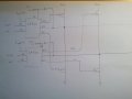
I'm using two LM5101 mosfet drivers to implement an h bridge for thermoelectric coolers (TECs). Each LM5101 makes a half h bridge. I left my schematic at work, but I have attached a rough sketch of the circuit (will post the real schematic tomorrow). I've left out some resistors, diodes, caps, pins, etc.
I was testing the circuit by applying the voltages as shown on the sketch to both LM5101s. Typically, I don't think you would want both high sides on at the same time, and they won't be when I implement the proper PWM. However, these voltages were actually what my microcontroller was outputting on reset.
With these voltages, I would expect both HS lines to have 24V on them, but I am not seeing this. In fact, I am seeing around 10-11 volts on those lines, and they are not the same voltage (they are around 1V off). The voltages I see at the gates of the FETs are also around the same voltage and are slightly off as well. I'm suspecting that the FETs aren't turned on completely, which is why the HS lines do not have 24V. Similarly, because one of the gate voltages on one of the FETs is higher, one of the HS lines has a higher voltage as well.
I have a 10 milli ohm current sense resistor on the top HS line and I noticed the voltage drop was 0.2V. I don't have any load attached, except for an LED and a 4.75K resistor so I'm not quite sure what's going on with the current draw as I was not expecting any.
Am I correct in expecting an even 24V on both HS lines? Or am I totally misunderstanding something...
Thanks!
I'm using two LM5101 mosfet drivers to implement an h bridge for thermoelectric coolers (TECs). Each LM5101 makes a half h bridge. I left my schematic at work, but I have attached a rough sketch of the circuit (will post the real schematic tomorrow). I've left out some resistors, diodes, caps, pins, etc.
I was testing the circuit by applying the voltages as shown on the sketch to both LM5101s. Typically, I don't think you would want both high sides on at the same time, and they won't be when I implement the proper PWM. However, these voltages were actually what my microcontroller was outputting on reset.
With these voltages, I would expect both HS lines to have 24V on them, but I am not seeing this. In fact, I am seeing around 10-11 volts on those lines, and they are not the same voltage (they are around 1V off). The voltages I see at the gates of the FETs are also around the same voltage and are slightly off as well. I'm suspecting that the FETs aren't turned on completely, which is why the HS lines do not have 24V. Similarly, because one of the gate voltages on one of the FETs is higher, one of the HS lines has a higher voltage as well.
I have a 10 milli ohm current sense resistor on the top HS line and I noticed the voltage drop was 0.2V. I don't have any load attached, except for an LED and a 4.75K resistor so I'm not quite sure what's going on with the current draw as I was not expecting any.
Am I correct in expecting an even 24V on both HS lines? Or am I totally misunderstanding something...
Thanks!
Attachments
-
 249.3 KB Views: 64