Hello, I found a board with the LM358 with a configuration that was a little strange for me. I would like to know if it is a non-inverter or inverter and calculate its gain.
Aschematic of the board
The op amp is being used as a non-inverting comparator.
Since there is no negative feedback, the gain equals the open-loop gain of the LM358.
R3 provides a small-amount of hysteresis to the trip point, but I'm not sure what D1 and D2 do since the D1 anode connection is not shown.
The power supply connections are also missing. Since the inverting (-) input is connected to a voltage divider between VDC1 and GND one might presume that the LM358 is powered by a single supply. Although that might be the case it would be good to know the actual situation.
Additionally… Without an input impedance, usually a resistor, on the noninverting input, the hysteresis value cannot be determined.
This is an incomplete circuit, it can’t even be classified as a circuit snippet.
If the signal goes to the -ve (inverting) input, then it is inverting.
If the signal goes to the +ve (non-inverting) input, then it is non-inverting.
Amplifier gain is determined by the feedback network from the output to the inverting input.
Since there is no feedback in the circuit, the gain is the open loop gain of the opamp and that is usually in excess of 100,000.
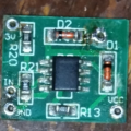
I forgot to put a photo of the board itself D2 is D1, D1 is D2, R20 is R1, R21 is R2 and R13 is R3 in the schematic, I assumed an ideal opamp in the schematic
Eric - R3 is connected to the non-inverting input.
In a normal 2-resistor hysteresis circuit, the two transition levels are symmetrical about the reference voltage. For example, with a reference voltage of approx. 0,8 V as in this circuit, the two transition levels could be 0.7 V and 0.9 V. As above, the amount of hysteresis depends on the source impedance of the input signal.
Enter diode D2. Now there is no current through R3 in one of the high output state. Thus, the transition levels no longer are symmetrical. In the negative-going direction, the output will change when Vin = 0.8 V. In the positive-going direction, the output is low and D3 is conducting. This adds 0.6 V to the feedback equation, which again is dependent on the input resistor.
With no impedance between the non-inverting input and V2, the V2 source impedance of 0 ohms swamps out the positive feedback, yielding identical transition levels.
 Facebook
 Google
 GitHub
 Linkedin